Top and bottom panel, Panel descr ip tions – Sound Devices PIX 220i User Manual
Page 8
10)
Record Button
Begins recording. Optional: Splits the
recording and begins writing a new
file when pressed while recording.
(System
Rec Button File Split
)
11)
Power LED
Hold the Menu button down, then press
the Control Knob to power on the unit.
12)
Time Code / Charge LED
Flashing green
: Accurate timecode is main-
tained by internal Li-Ion battery.
Flashing amber
: battery charging. (Time-
code display has precedence)
Alternating Amber / Green
: Fault with
internal timecode battery.
Solid Red (when PIX is powered up)
: Time-
code has been reset back to zero and
needs to be re-jammed due to PIX power
being off for more than 2 hours.
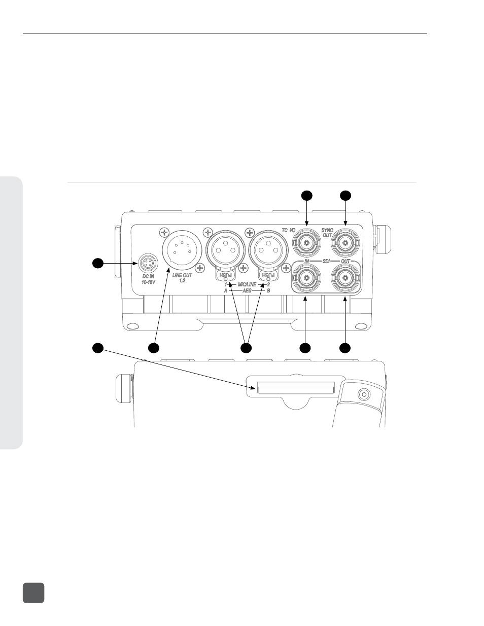
Top and Bottom Panel
3
2
1
4
8
7
6
5
1)
CompactFlash Slot
Insert CompactFlash media with the
label-side up. V
for an up-to-date list of tested
and approved cards.
2)
External DC Input (Hirose 4-pin)
Accepts 10–18 volts DC. Hirose 4-pin con-
nector is wired pin-1 negative (-), pin-4
positive (+).Pin-2 (-) and pin-3 (+) must
be connected in parallel to pins 1 and 4
respectively to charge attached Li-ion
batteries. The included XL-WPH3 power
supply provides positive DC on pins 3
and 4 and negative DC on pins 1 and 2.
3)
Audio Output - 5-pin XLR
Two channels of active, balanced, line-
level output. Source selected in the Audio
Menu.
4)
Audio Inputs - 3-pin XLR
Active, balanced, analog microphone
or line level inputs.
PIX 240i only: can
be switched to accept AES digital input,
channels.
PIX 220i and PIX 240i Video Recorder User Guide
6
v. 3.52
Features and specifications are subject to change. Visit www.sounddevices.com for the latest documentation.
Panel Descr
ip
tions