Rite-Ride 2518 User Manual
Page 7
use a PVC cutter, side cuts, scissors, or anything that will
crush or squeeze the line while cutting. When installing
the tubing into a fitting, push the tubing into the fitting
until it bottoms out. Avoid sharp bends in the tubing as
they may buckle over time.
From the compressor, cut a length of tubing about
3-4 inches long. Attach one end to the compressor tee
fitting and the other to a tee fitting. Route one branch
to the tank and the other to the valve block inlet.
See
Figure “O”.
Route tubing that runs from the valve block to each
air spring, individually. Attach the tubing to the air spring.
Cut the line between the valve block and each air spring
and install a tee fitting. Use the open branch of the tee
to run airline to a location where an inflation valve can
be mounted, protected and accessed easily with an air
chuck. The rear bumper near the license plate provides
a good location for a secure mounting location. Drill a
5/16" hole to accept the inflation valve if needed. Attach
the inflation valve and complete the air line connection.
See Figure “O”.
STEP 10: PLACING THE VEHICLE BACK ON
THE GROUND
Using the manual inflation valves, slowly inflate the air
springs to 15-20 psi. Ensure the sleeves are rolling over
the pistons and are not bound or twisted.
See Figure
“P”, “Q”, & “R”.
Reinstall the wheels but leave the fender liner off.
Slowly lower the vehicle to the ground, checking fre-
quently to make sure the sleeves continue to roll over
the pistons.
See Figure “P”, “Q”, & “R”.
Once the vehicle is on the ground, increase the
pressure in the air springs so that the measurement from
the lip of the wheel to the lip of the fender is exactly the
same as the recorded measurement from the beginning
of this installation.
NOTE: THE AIR SPRINGS MAY HAVE
DIFFERENT PRESSURES AT THE CORRECT RIDE
HEIGHT. See Figure “A”.
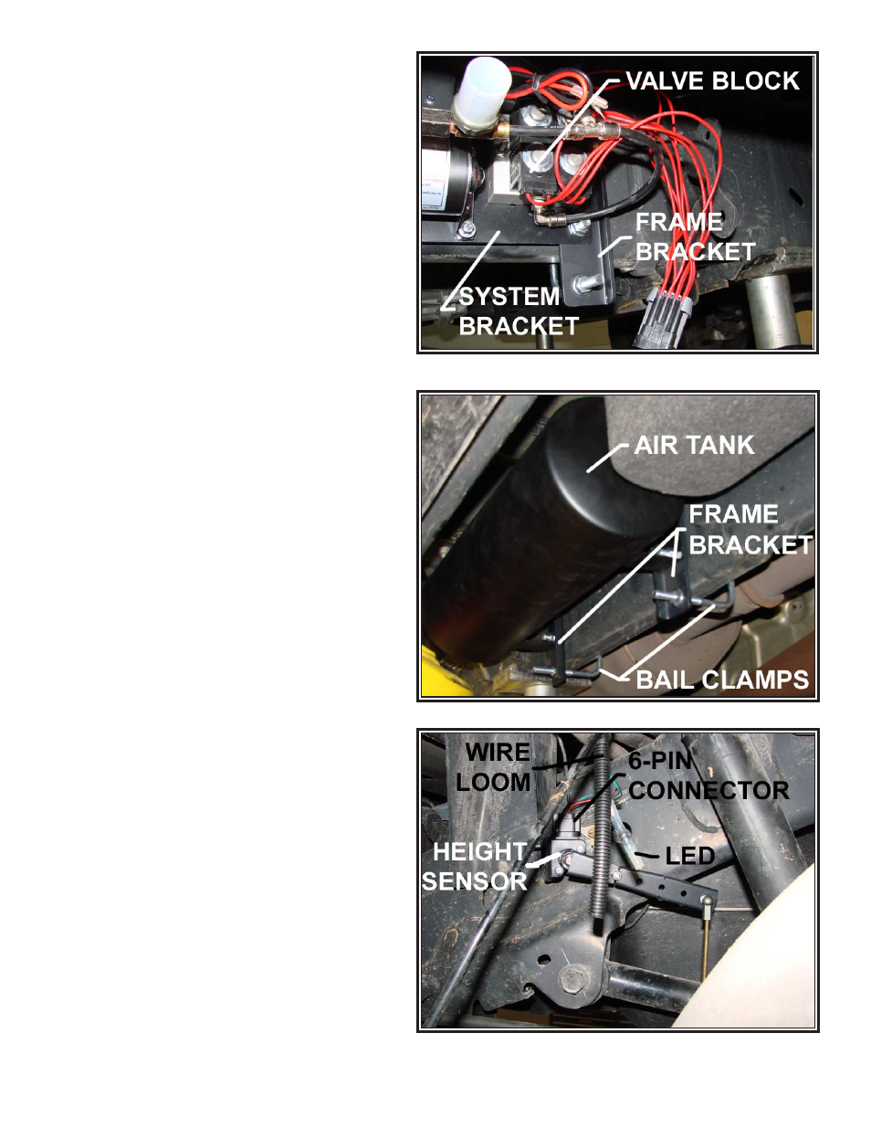
STEP 11: SETTING RIDE HEIGHT
Find a fuse that is active at +12VDC when the ignition is
on (M49 position). Insert the fuse tap into the fuse box
and secure.
Attach the red wire with the in-line fuse from the
harness to the positive terminal of the battery. Attach
the black wire from the harness to the negative terminal
of the battery.
Turn the ignition to the vehicle ‘on’ position. The
compressor will start running to fill the air tank to 120
psi. Once complete, the height sensor linkages can be
installed.
See Figure “S”.
Hand tighten one sensor linkage to each end of the
two M5 threaded rods. The openings should be facing
in opposite directions after being tightened. Using pliers,
carefully snap the socket of the sensor linkage onto the
ball of the height sensors brackets. It is very important
that the height sensor arm is parallel with the ground and
the LED is illuminated. If the LED is not illuminated, adjust
the length of the threaded rod until the LED is glowing.
Reinstall the fender liners.
Finally, plug the 8-pin connector from the wire har-
ness into the valve block. See
Figure “T”.
Figure “J”
Figure “K”
Figure “L”