Rite-Ride 2518 User Manual
Page 4
STEP 1: PREPARE THE VEHICLE
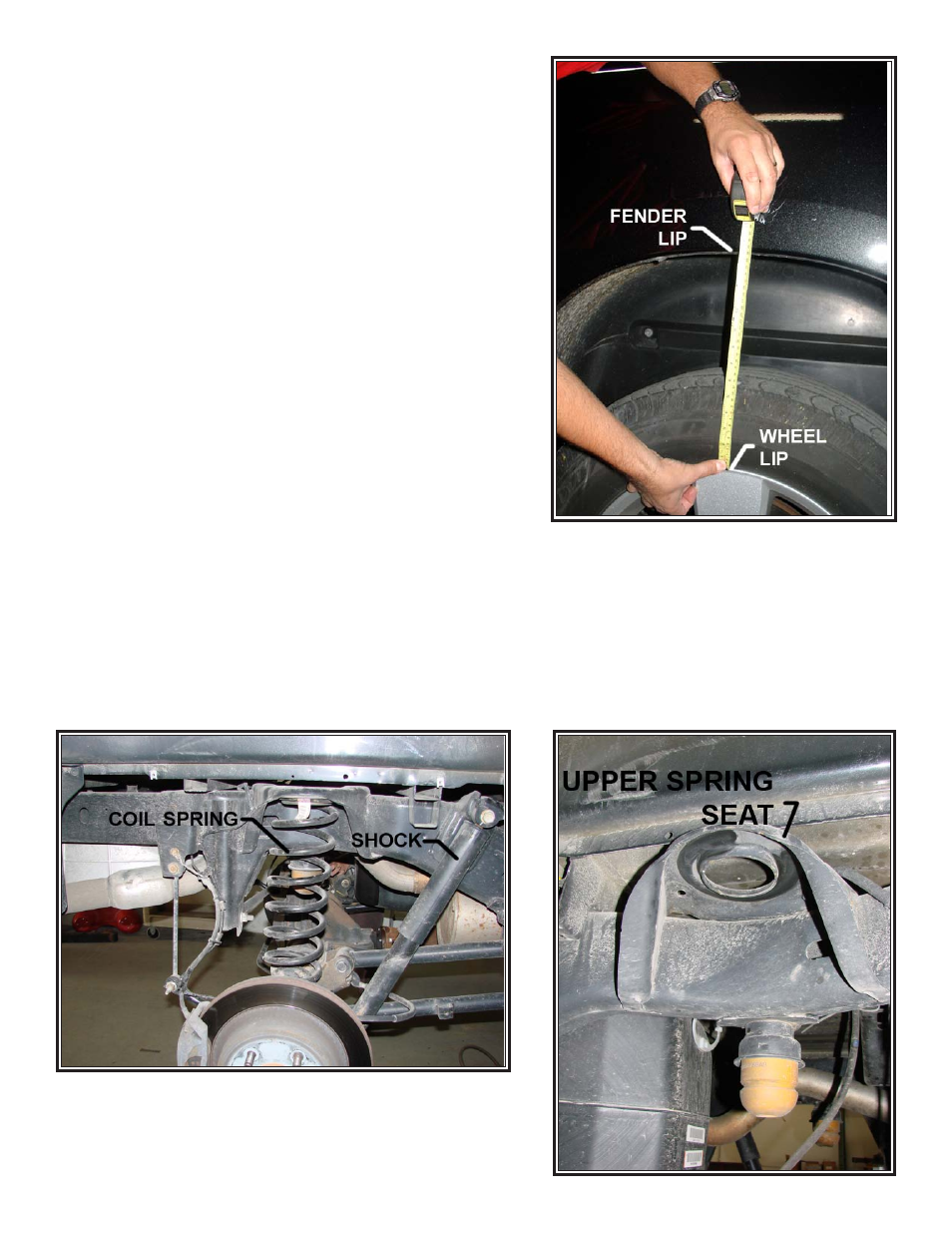
Place the vehicle on a flat surface. Measure and record the ride height
on Page 2. The most accurate way to measure this height is to measure
from the lip of the wheel rim to the fender directly above the wheel
(Figure “A”).
Raise the vehicle, or the rear of the vehicle, to allow the suspen-
sion to relax and remove the wheels. Remove the fender liner on both
sides of the vehicle.
STEP 2: REMOVE STOCK COIL SPRINGS
Support the rear axle with axle stands rated for the vehicle’s weight.
Remove the lower shock bolt on both sides of the vehicle.
See Figure
“B”. The shocks can be completely removed for clearance during
installation, but it is not required.
Allow the axle to extend completely and remove the coil springs and
upper mounts on both sides of the vehicle.
See Figure “C”.
STEP 3: PREASSEMBLE THE AIR SPRINGS
Install the air fitting on each air spring. Tighten the fitting to engage
the nylon ring, then tighten and additional 1/2 turn. Install the threaded
studs to the top of the air spring. Slide the upper mount
(5690) over
the studs so the flat surface is touching the top of the air spring. Set
the preassembled air springs aside.
STEP 4: MOUNT THE HEIGHT SENSORS
Attach the height sensor extension arm to the height sensor using a
M6-1.0 X 12mm bolt and M6 nylock. Attach one M5 sensor linkage with
the ball towards the outside and in the hole farthest from the height
sensor. Use a M5 nylock to secure to the arm.
See Figure “F”.
On the passenger side, use the provided M8-1.25 X 15MM bolt and M8 washer to mount the lower linkage bracket
to the vehicle’s lower suspension linkage. There is an unused weld nut on the lower arm forward of the axle. The bracket
should point up once installed. Attach one M5 sensor linkage to the other hole in the bracket so the ball faces inboard.
Secure with a M5 nylock nut.
See Figure “F”.
On the driver side, remove the M8 bolt that holds the emergency brake cable bracket. The bracket should be installed
between the weld nut and the brake cable bracket. Install the lower linkage bracket and reinstall. Attach an M5 sensor
linkage and secure with an M5 nylock nut.
See Figure “G”.
The height sensors are marked L (left) and R (right). When mounted, the electrical plug should face up and the arm
should rotate towards the rear of the vehicle. Brackets should have the open end facing towards the rear of the vehicle and
Figure “A”
Figure “C”
Figure “B”