Rite-Ride 2518 User Manual
Page 6
Attach the relay to the plate where it will be accessible
in the future. Secure using one 10-32 X 3/4" machine screw
and nylock nut.
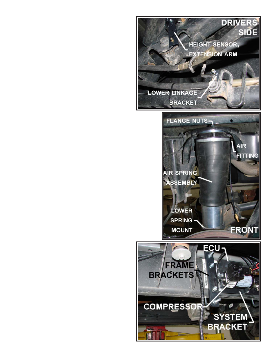
STEP 7: MOUNT THE SYSTEM PLATE AND
TANK TO THE VEHICLE
Select the air tank from the kit and install the 1/4 NPT
plug into one end and the 1/4 NPT elbow fitting into the
other end. Tighten the fittings to engage the orange thread
sealant. Mount the tank to two frame brackets using four,
3/8"-16 flange nuts.
See Figure “K”.
Mount the tank assembly to the passenger side frame
rail using two bail clamps and four 3/8"-16 flange nuts.
It should be located on the outside of the frame rail just
forward of the fender well.
See Figure “K”.
Mount the preassembled system plate to two frame
brackets using four 3/8"-16 flange nuts. Mount the system
plate assembly to the frame using two bail clamps and four
3/8"-16 flange nuts. The plate should be on the outside
of the frame rail, just forward of the tank assembly.
See
Figure “I” & “J”.
NOTE: It is important that the system plate assembly is located on
the passenger side frame rail.
STEP 8: INSTALL THE WIRE HARNESS
Uncoil the wire harness and locate the 16-pin ECU connector. Route
the portion of the harness with the two height sensor connectors (6-pin)
along the frame rail towards the rear of the vehicle. Route the driver
side height sensor connector through the hollow cross-member under
the bed to the other side of the vehicle. Once the connections have
been made at the height sensors, peel back the wire loom to expose
the LED for each side. Ensure the LED is easily visible.
See Figure “L”.
Make the connection at the relay. Ground the compressor lug to a
suitable location on the chassis. Attach the red wire (male spade) from
the relay to the red wire (female spade) on the compressor. Attach the
blue wire from the relay to one side of the pressure switch. Attach the
black wire (female spade) in the harness to the other side of the pres-
sure switch.
NOTE: DO NOT INSTALL THE 8-PIN PLUG FOR THE
VALVE BLOCK AT THIS TIME.
Route the remaining wire harness forward along the frame rail and
into the engine compartment, staying as far away as possible from
potential heat sources. Run the wire across the back of the engine
compartment, securing the loom to firewall.
See Figure “M”.
Once the harness is on the driver’s side by the fuse
box and battery, route the three wires for the kneel switch
through the firewall. Crimp the provided fuse tap to the
yellow wire.
NOTE: DO NOT COMPLETE THE CONNECTION TO THE
FUSE BOX OR THE BATTERY AT THIS TIME.
In the cabin, route the three wires and loom to the final
location of the kneel switch. The location of the switch
should be easily seen, but not accidentally hit. The switch
will glow red when the vehicle is kneeled. During normal
operation, the switch will not be illuminated. A bracket and
self-tapping screws, 10-16 X 1/2, have been provided to
mount the switch, but they do not need to be used.
NOTE:
A 20MM hole will need to be drilled for the switch if the
bracket is not used. After the switch is mounted, connect
the wires to the male spade terminals on the back of the
kneel switch. See Figure “O”.
STEP 9: AIR LINE INSTALLATION
DO NOT FOLD OR KINK THE TUBING. The tubing should
have square cuts using the supplied tubing cutter. DO NOT
Figure “I”
Figure “H”
Figure “G”