Icon series lts 1.0 – HK Audio IC 118 BA User Manual
Page 8
Icon Series LTS 1.0
• Through
This parallel output serves to forward the incoming
line signal.
• Sub Output
This output sends the low-frequency signal from the
IC 112 LA mid/high unit to the ICON IC 118 BA Sub
via an XLR cable. Ensure XLR connectors are wired
as follows: 1= ground, 2= +, 3= -.
• BVNet In/Link
Connect the BVNet interface’s output to the first
mid/high unit’s In port. Then connect the Link port
to the next mid/high unit’s In port. Follow the same
procedure to connect further components equipped
with DSP modules.
• Sub Link In Port - Internal System Guard
You can monitor the entire system’s performance
if you connect the IC 118 BA subwoofer to the
mid/high unit via the Internal Link ports using a
standard Ethernet cable (RJ45).
• PowerCon Mains Input
Twisting the PowerCon connector until locks
switches on the speaker cabinet. Use the factory-
included PowerCon mains cord to connect this
socket to a wall receptacle. Caution! Make sure the
local mains voltage matches the voltage specified
on the device. Connecting the system to the wrong
mains voltage may destroy the ICON system’s
electronic components.
Heads up: Current consumption may not exceed 16
amps per phase, which comes to 3,600 watts at 230
volts. This means each phase can power no more
than one ICON LTS stack comprising one mid/high
unit and two subwoofers. These values may vary
depending on the country, voltage, and venue. Be
sure to check how much power the mains supply
provides in watts or amperes before you switch the
system on. Always switch ICON components on one
after another rather than all at once to keep inrush
currents as low as possible. High inrush current can
trip the venue’s mains fuse.
The IC 112 LA’s LED Indicators
• Limit LED
This LED indicates the Class D power amps’ peak
limiter has engaged to attenuate a maximum output
voltage excursion, or put simply, a clipping signal.
• Signal LED
This LED lights up when the unit detects an
incoming signal with -56 dBU.
• Power ON LED
This LED lights up when a mains power supply is
connected.
• Temp. Limit
This LED lights up when one of the three integrated
sensors detects that electronic components have
reached critical temperature. The power amp
attenuates the signal by 6 dB until the temperature
drops back to the normal operating range, at which
time the LED extinguishes.
• Amp
This LED lights up
- for about five seconds while amp powers up
when the device is switched on, after which it
extinguishes.
- continuously to indicate the device has been
muted for its own protection, possibly due to some
flaw in the amp. The device definitely requires
service.
- when the amp is up and running and an error
occurs, for example, if it is operating at peak level
while driving speakers whose impedance is too
low. The LED extinguishes when the amp’s power
output is reduced.
• Wink LED
Sited in the mid/high unit’s front grille, this yellow
LED flashes several times when address the DSP
module in PodWare; that is, when you click the
Locating button on the application’s user panel.
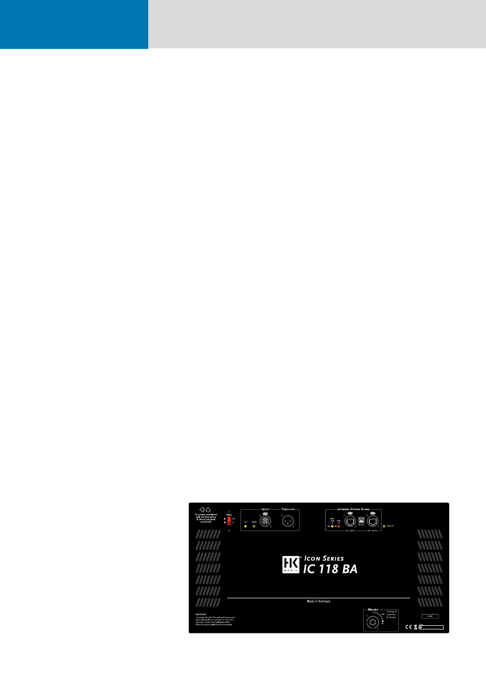
3.2 ICON IC 118 BA
The IC 118 BA’s Control Features
• Phase
Use this switch to determine the IC 118 BA’s polarity.
0°: The IC 118 BA’s polarity is positive (in phase).
180°: The IC 118 BA’s polarity is negative (out of
phase).
The IC 118 BA’s polarity is positive (in phase) when
it is connected to the IC 112 LA.
The IC 118 BA’s Cable Connections
• Input
Use a balanced XLR cord to connect the IC 112 LA
mid/high unit’s Sub Out port to this balanced input
and route the signal from the ICON controller to
the subwoofer. Ensure XLR connectors are wired as
follows: 1= ground, 2= +, 3= -. The IC 118 BA’s input
sensitivity is +4 dBu.
Heads up: Never patch the mixer's line or master
signal directly into the subwoofer’s Input. This
bypasses the system’s controller, crossover,
equalization, and protection circuits, risking serious
damage to the subwoofer. Read chapter 2, Setup
and Cable Connections, for more on this.
• Through
This parallel output serves to forward the incoming
subwoofer signal to another IC 118 BA using an XLR
cord. Ensure XLR connectors are wired as follows:
1= ground, 2= +, 3= -.
The IC 118 BA’s LED Indicators
• Limit LED
This LED indicates the Class D power amps’ peak
limiter has engaged to attenuate a maximum output
voltage excursion, or put simply, a clipping signal.
• Signal-LED
This LED lights up when the unit detects an
incoming signal with – 56 dBU.
• Power On LED
This LED lights up when a mains power supply is
connected.
Fig. 10: The ICON IC 118 BA’s control features