Icon series lts 1.0 – HK Audio IC 118 BA User Manual
Page 10
Icon Series LTS 1.0
Installing BVNet-Modul Interface
To learn more about installing the BV Net Interface, please read the User Guide
that comes with it.
4.4 How to Handle the Software
• A double-click launches PodWare once it has been installed.
• Connect the ICON system to the BVNet interface, and then connect the laptop:
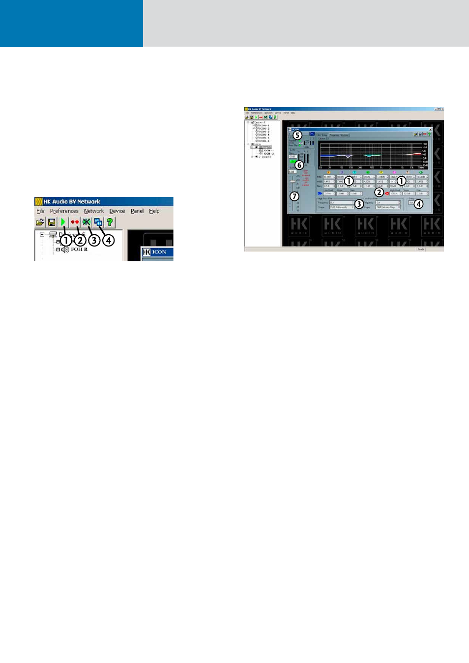
Figure 12: The PodWare’s basic functions
1 Net Scan: PodWare scans the entire network, searching for connected devices.
2 Locating: This is a convenient way of identifying a device – that is, the DSP
module in a mid/high unit – when several devices are connected and their
panels are open in PodWare. Simply click this icon and watch the Wink LEDs to
see which one flashes.
3 Mute: This button mutes all devices connected to the network.
4 Launch all Panels: This function opens the panels of all devices connected to
the network.
PodWare generated a device panel for every connected speaker cabinet equipped
with a DSP module. You can view, edit, and monitor parameters and controlling
functions at two different window levels in this device panel.
The EQ/ Delay Device Panel
Figure 13: The EQ/ Delay device panel
1 Equalizer with 8 fully parametric bands: Variable parameters: Freq: 10 Hz to
25.6 kHz, Quality: -> 0.17 to 14.2 Q factor or -> 0.102 to 5.25 octaves
Gain: -15 dB to +15 dB. Use the mouse to operate the EQ or enter values direct-
ly. You can’t link devices, but you can copy and paste EQ settings.
2 Low-shelf /high-shelf filters: Variable parameters: Freq: 10 Hz to 25.6 kHz,
Slope: 6dB to 12dB, Gain: -15 dB to +15 dB. If you want to apply values from
one device to another, you must copy and paste them.
3 Low-pass / high-pass filters: Variable parameters: Freq: 20.2 Hz to 25.6 kHz,
filter type: 1st order (Bessel, Butterworth, Linkwitz-Riley, and Bessel with 12, 18,
and 24 dB each). You can copy and paste individual values only.
4 Delay: Variable in time (0.0116 ms to 201 ms) and distance (metric units:
3.97 mm to 69 m; imperial units: 0.01 ft to 226 ft).
5 Status: Indicates the current operating status
• Driver: Indicates speaker impedance: (green = ok, red = the impedance has
changed)
Note: A permanent change in impedance may indicate a defective speaker.
• Amplifier Clip: Indicates the amplifier is clipping.
6 Gain Indicators:
• Panel for the signal level.
• The LIM A and B boxes show the status of the DSP module’s software
limiters.
7 Gain Knob: This control adjusts levels, and the display panel shows the knob
setting.