Motor and speed control installation – E-flite Nieuport 17 250 ARF User Manual
Page 12
12
E-flite Nieuport 17 Slow Flyer Assembly Manual
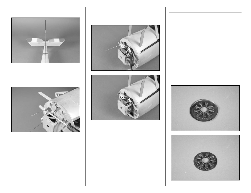
7. Align the rudder with the center line of the
fuselage to center the control surface.
8. Use a #1 Phillips screwdriver to tighten the
1.5mm machine screw that will secure the pushrod
wire in the pushrod connector. Use threadlock on
the screw to prevent it from vibrating loose in flight.
9. Use diagonal cutters to trim the excess pushrod
wire extending from the servos. If this is not
trimmed it will interfere with the operation of the
motor.
Motor and Speed Control Installation
Required Parts
Fuselage assembly Dummy motor
Motor
Speed control
Propeller
Motor battery
Cowling
Tie wrap (not included)
Two-sided tape
Carbon tube, 6mm x 42mm
2mm x 8mm wood screw (black) (3)
Required Tools and Adhesives
Foam-safe CA
Phillips screwdriver: #1
Hobby scissors
Hobby knife w/#11 blade
RTV Silicone
Hook and loop tape
Medium grit sandpaper
1. Use hobby scissors to remove the excess material
from around the dummy motor. A line has been
molded in the dummy motor to use as a guide.
- Habu 32x DF ARF (84 pages)
- A6M5 Zero 300 BNF Basic (17 pages)
- Hawker Sea Fury 480 ARF (28 pages)
- Mystique RES 2.9m ARF (52 pages)
- Super Cub 25e ARF (48 pages)
- AT-6 Texan 25 ARF (52 pages)
- LR-1A Pogo ARF 15e (21 pages)
- J-3 Cub 450 (40 pages)
- Hawker Hurricane 25e PNP (26 pages)
- Hawker Hurricane 25e PNP addendum (1 page)
- Apprentice 15e PNP (28 pages)
- Sukhoi SU-26m 480 ARF (28 pages)
- Beechcraft Bonanza 15e ARF (60 pages)
- Byp Yak 3D ARF (40 pages)
- Ultimate Fx 3D ARF (40 pages)
- Tribute FX 3D ARF (28 pages)
- Sobre 3D Profile (32 pages)
- Ascent EP Park Glider ARF (23 pages)
- Float Set Complete: Carbon-Z Cub (2 pages)
- Carbon-Z Cub PNP (27 pages)
- Carbon-Z Cub PNP Addendum (1 page)
- BAe Hawk 15 DF ARF (36 pages)
- Edge 540QQ 280 BNF Basic (19 pages)
- P-40 Warhawk 300 ARF (20 pages)
- Hawker Sea Fury 400 ARF (40 pages)
- Clipped Wing Cub 250 ARF (40 pages)
- T-34 Mentor 25e ARF (28 pages)
- Ultra Stick 25e ARF (40 pages)
- Ultra Stick 25e ARF Programming Guide (5 pages)
- Slick 3D 480 ARF (48 pages)
- PT-19 450 ARF (44 pages)
- Extra 330SC BP 3D ARF (40 pages)
- Cap 232 BP ARF (44 pages)
- Brio 10 ARF (56 pages)
- Park 480 BL Motor Combo (4 pages)
- Mini Edge 3D ARF (44 pages)
- Cessna 182 370 ARF (32 pages)
- Cessna 182/Park 400 BL Motor Combo (4 pages)
- Tribute 3D Profile ARF (40 pages)
- Fokker DVII 250 ARF (28 pages)
- Enticement F3P ARF (36 pages)
- Carbon-Z Yak 54 3X BNF Basic (23 pages)
- Carbon-Z Scimitar PNP (28 pages)
- UMX B-17G Flying Fortress BNF (18 pages)
- UMX Sbach 342 3D BNF Basic (17 pages)