Landing gear installation – E-flite F-16 400 DF ARF w/Motor & Fan Unit User Manual
Page 9
9
E-flite F-16 ARF Assembly Manual
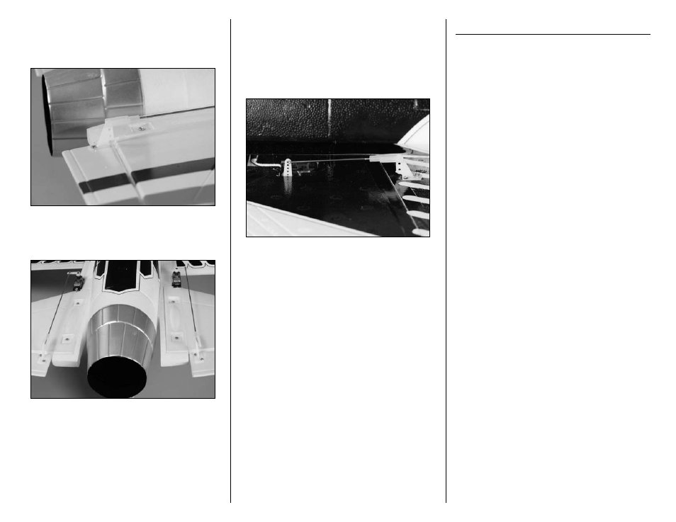
14. Attach the clevis on the pushrod to the
outer hole of the elevator control horn. Snap
the clevis together so it is secure on the
control horn.
15. Repeat Steps 13 and 14 to install the second
elevator linkage. The left and right linkages will be
mirror images of each other when installed.
16. Repeat Steps 13 and 14 to install the 2
7
/
8
-inch
(73mm) pushrod wire with clevis for the ailerons.
The end at the servo will attach to the outermost
hole in the aileron servo arm, and the clevis will
attach to the outer hole on the control horn as
shown. Make sure to install both the left and right
aileron linkages at this time.
Landing Gear Installation
Required Parts
2mm nut
Servo
Assembled fuselage
Long 3D servo horn
Nose gear wire w/wheel
Gear door (right and left
Main landing gear w/wheels
2mm x 10mm machine screw
Brass steering arm bushing
1/16-inch wheel collar w/screw
Nose gear steering arm w/screw
2mm x 8mm self-tapping screw (4)
Required Tools and Adhesives
Side cutter
Pin drill
6-minute epoxy
Mixing cup
Mixing stick
Epoxy brush
Paper towel
Rubbing alcohol
Threadlock
Sandpaper
Hobby knife w/#11 blade
Drill bit: 5/64-inch (2mm)
Phillips screwdriver: #00, #1
Note: The landing gear assembly is optional.
The F-16 can be flown with or without the
landing gear.