Speed control and receiver installation – E-flite F-16 400 DF ARF w/Motor & Fan Unit User Manual
Page 13
13
E-flite F-16 ARF Assembly Manual
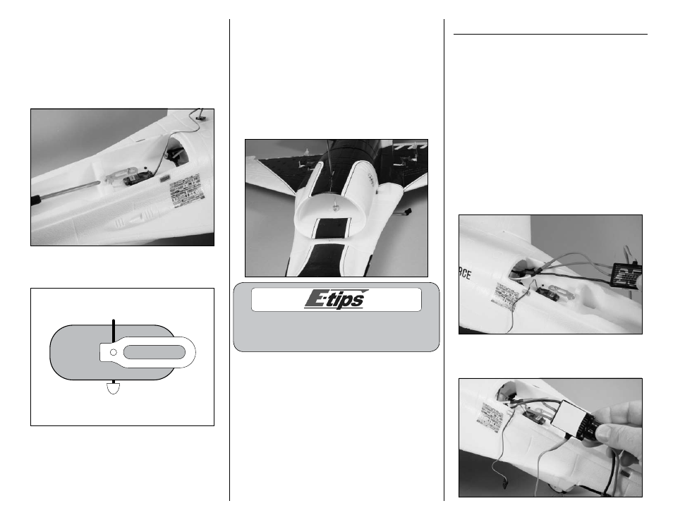
18. The nose gear will slide into the hole in the
steering arm as its final destination. The screw
at the steering arm will then be tightened so it is
resting in the flat area as indicated back in Step
14. Use a #1 Phillips screwdriver to tighten the
screw in the steering arm. Always remember to use
threadlock on metal-to-metal fasteners to prevent
them from vibrating loose.
Note: The steering arm and wheel will be
parallel to each other as illustrated below.
19. Position the gear so there is a gap of
1/32-inch (.5mm) between the steering arm and
the servo horn so they do not bind during the
operation of the nose gear. With the wheel collar
resting lightly against the fuselage as shown, use
a #1 Phillips screwdriver to tighten the screw in
the wheel collar. The screw at the wheel collar
will be tightened so it is resting in the flat area
as indicated back in Step 14. Always remember
to use threadlock on metal-to-metal fasteners to
prevent them from vibrating loose.
You can place a piece of paper between the
steering arm and servo arm to achieve the correct
amount of gap before securing the wheel collar.
Speed Control and Receiver Installation
Required Parts
Speed control
Assembled airframe
Receiver
Hook and loop tape
Note: Due to the current draw of the system
and the location of the electronics. We
recommend that throttle management is used
during each flight. Using full power throughout
the duration of the flight will result in shorter
flight times and could result in a shorter life
span for the electronics and batteries.
1. Plug the wires from the speed control and motor
together. The wires from the motor will be just long
enough that they can be accessed from the cockpit
area of your model.
2. Apply a small piece of hook and loop tape to
the bottom of the speed control.