E-flite F-16 400 DF ARF w/Motor & Fan Unit User Manual
Page 8
8
E-flite F-16 ARF Assembly Manual
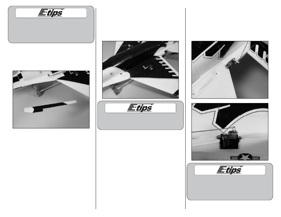
Before inserting the extension leads through the
fuselage, mark each lead according to which servo
it is connected to. (Right Elevator, Left Elevator-
this will help with set up later). You can use a
small tip marker or a piece of tape for this.
11. Locate the decal to cover the channel for the
aileron and elevator extensions. A right and left
decal has been supplied to cover the channels.
Make sure to use the correct decal on each side of
your aircraft.
12. Remove the backing from the decal. Starting
at the front, hold the rear of the decal up and
align the trim scheme from the decal to the
scheme on the aircraft. Carefully work toward
the rear of the fuselage, pressing the decal down
and guiding the extensions under the decal to
remain in the channel.
A water-based dark blue paint can be used to
paint the exposed white foam that is shown on
the wing where the servo lead runs through.
13. Insert the end of the 5
7
/
8
-inch (150mm)
pushrod wire with the clevis and “Z” bend
into the hole of the servo arm that is in one
hole from the end of the horn as shown. The
pushrod will enter from the top of the horn.
Insert the wire so it appears as shown in the
second image.
You may have to slightly enlarge the hole in the servo
horns for the pushrod wire. Use a sharp #11 blade
to do this by twisting it in the hole on the top and
bottom of the servo arm. Do this a small amount at
a time as it will not need to enlarge the hole much.