Preventive maintenance – Watts Autotrol 263 / 268 (400 Series) User Manual
Page 10
10
Preventive Maintenance
Injector Screen and Injector
Inspect and clean brine tank and screen filter on end of
brine pickup tube once a year or when sediment
appears in the bottom of the brine tank.
Clean injector screen and injector once a year:
1. Unplug the wall-mount transformer.
2. Shut off water supply or put bypass valve(s) into
bypass position.
3. Relieve system pressure by opening valve No. 7
(at rear) with a screwdriver (Figure 10).
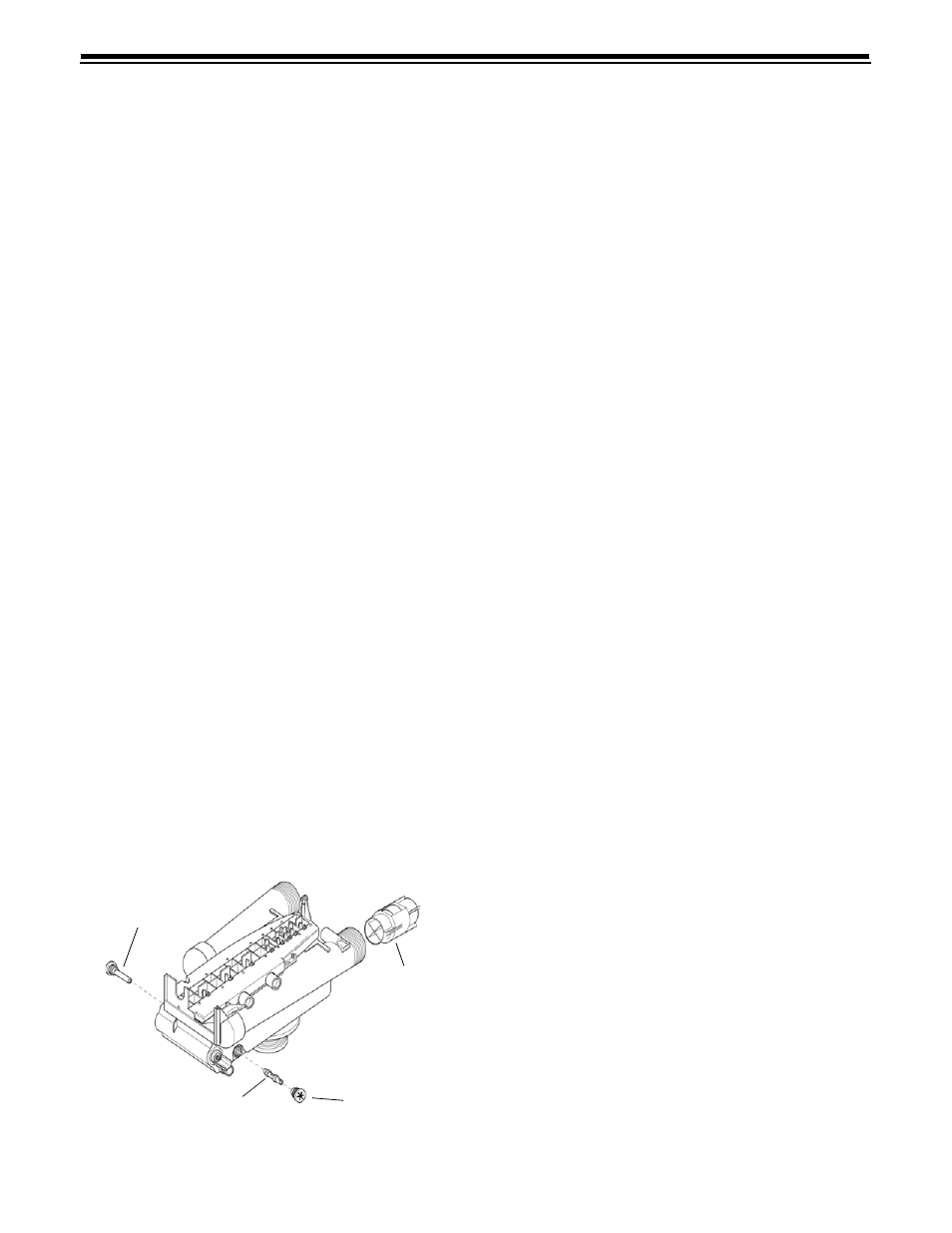
4. Using a screwdriver, remove injector screen and
injector cap (Figure 13).
5. Clean screen using a fine brush. Flush until clean.
6. Using a needle-nose pliers, pull injector straight
out.
7. Flush water into the injector screen recess of the
valve body to flush debris out through the injector
recess.
8. Clean and flush the injector.
9. Lubricate the O-rings on the injector, injector cap
and injector screen with silicone lubricant only!
10. Reinstall the injector, injector cap and injector
screen.
IMPORTANT:
Do not overtighten the plastic cap. Seat
the cap lightly into position. Overtightening may cause
breakage of the plastic cap that may not be
immediately evident.
11. Plug the wall-mount transformer into outlet; reset
clock if necessary.
12. Slowly open water supply valve or return bypass
valve(s) to the “service” position.
Figure 13
Water Meter Maintenance
Note: A water meter is used only with the 460i control.
If you are using the 440i control, this section does not
pertain to your conditioner.
The metering device used with the 460i demand control
may require simple maintenance. In rare instances, the
turbine wheel of the water meter can collect small
particles of oxidized iron, eventually preventing the
wheel from turning.
1. Shut off the water supply or put the bypass valve(s)
into the bypass position.
2. Relieve pressure by opening the Backwash Drain
Valve (the seventh back from the control) with a
screwdriver (Figure 10).
3. Loosen and remove the pipe/tube adapters or
1265 bypass from the inlet and outlet of the valve
body.
4. Using a needle-nose pliers, remove the turbine
from the outlet housing. Grasp one of the four
vanes of the outer gland and pull straight out to
remove turbine assembly from the outlet of the
valve (Figure 13).
5. Carefully remove the turbine wheel from the
housing. Use a toothbrush to lightly scrub the iron
off the magnet. Iron buildup on the surfaces can be
removed by soaking the wheel in a mild sodium
hydrosulfite (such as RoVer*) solution for a few
minutes. Flush thoroughly with water.
6. Carefully reinstall the turbine wheel into the turbine
cage housing. Make sure that the shaft of the wheel
seats into the bearing of the cage. Reassemble the
turbine cage and check that the wheel rotates
freely.
7. Reinstall the turbine cage into the outlet of the
valve.
8. Reinstall the pipe/tube adapters or 1265 bypass to
the inlet and outlet of the valve.
9. Turn on the water supply or put the bypass valve(s)
into the service position and purge the air out of the
system.
To check for proper meter operation, open a
downstream faucet and observe the water flow
indication on the control display.
Injector
Injector Screen
Cap
Turbine
*RoVer is a trademark of Hach Chemical Company
.