C. electrical, D. startup, E. control function – Watts PWR2511 User Manual
Page 4
4
C. Electrical
Note: It is the responsibility of the end user to ensure that the
installation is done according to local codes and regulations.
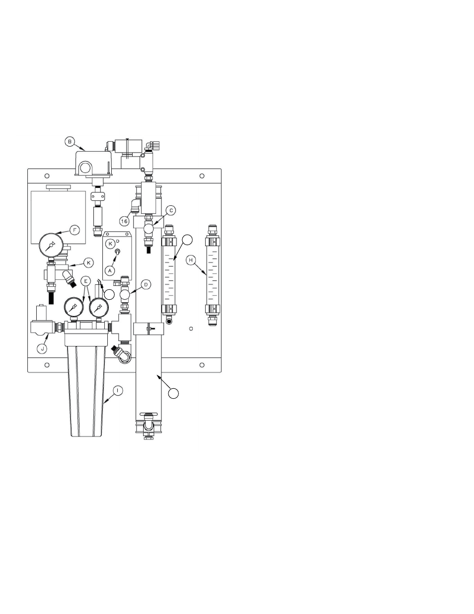
1. Make sure the on / off switch is in the off position (Figure # 1
item A).
2. Plug the unit into a standard 120 volt 3 prong outlet. An outlet
protected with a ground fault interrupt (GFI) is recommended.
D. Startup
1. Verify that the pretreatment equipment is installed and working
properly. Verify that no free chlorine is present in the feed water.
2. Verify that the on / off switch is in the off position.
3. Install a 10" five micron filter cartridge in the prefilter housing.
4. Open the reject control valve completely (Figure # 1 item C) by
turning it counterclockwise.
5. Close the reject recycle control valve (Figure # 1 item D) com-
pletely by turning it clockwise.
6. Open the feed water shutoff valve installed in step III-B-1 above.
7. Move the controller on/off switch to the on position.
8. Allow the unit to run for 15 – 30 minutes to flush the preservative
from the membrane(s).
9. Adjust the reject control valves (Figure # 1 items C & D) until the
desired flows are achieved. Closing the reject valve increases
the product flow and decreases the reject flow. Opening the
reject recycle valve decreases both the reject and product flow.
See the flow rate guidelines and temperature correction table in
the appendix to determine the flow rates for different operating
temperatures. Do not exceed 200psi on the pump discharge
gauge (Figure #1 item F).
10. Allow the product water to flow to drain for 30 minutes.
11. Turn off the system and connect the product line to the point of
use. The product water line should never be restricted. Mem-
brane and/or system damage may occur if the product line is
blocked.
12. Restart the system and record the initial operating data using the
log sheet.
E. Control Function
1. When the on / off switch is in the on position, the inlet valve
opens and the pump runs. If the product pressure switch is used
then the pump will cycle based on the product water pressure.
The switch is factory set to cut off at 40psi and cut on at 20psi.
Instructions for adjusting the cut off and cut on pressures are
located on the inside cover of the switch.
2. If the water pressure feeding the pump drops below 5psi for more
than 5 seconds, the pump will turn off and the amber light on the
control box will turn on. The controller will automatically reset after
30 minutes and the pump will turn back on. Cycle the on / off
switch to manually reset a low-pressure shutdown.
3. Autoflush – This is a feature that provides increased reject flow
at startup and for 2 minutes every hour. The timer is prepro-
grammed at the factory and should not be adjusted.
Figure 1
G
M
L
Figure 1