Reverse osmosis module mounting, Adapt-a-valve™ installation, Configuration for – Watts PWROKCZRO User Manual
Page 5: Configuration, Step 4, Step 2, Step 3
5
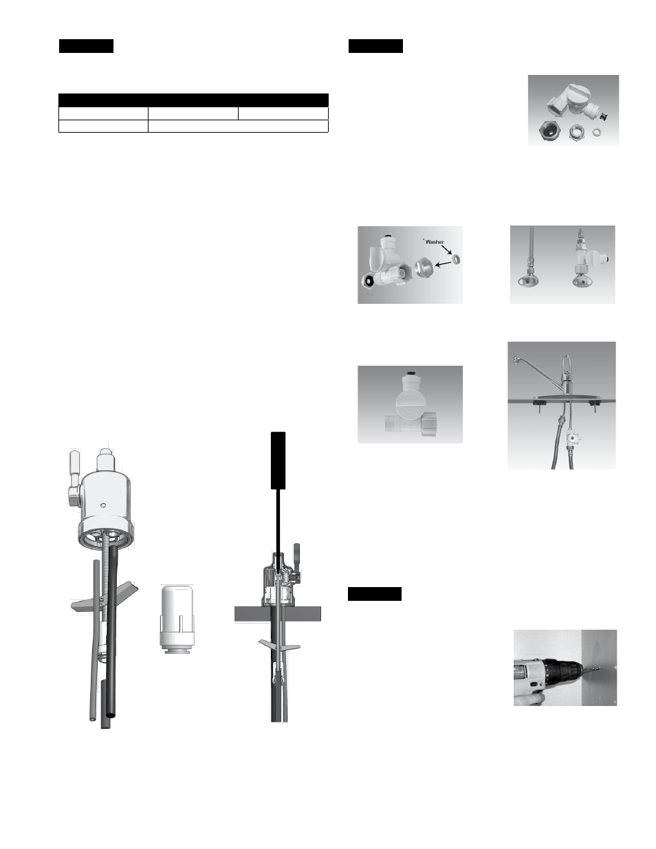
STEP 4
Reverse Osmosis Module Mounting
Step A – Determine best location for the
RO module to be mounted to
allow for future system main-
tenance . The parts bag has 2
self tapping screws . Using an
electric drill with a Phillips bit,
screw them into the cabinet
wall 6" apart and 16" from the
bottom of the cabinet .
Note: Do not cut any RO system tubes at this time
STEP 2
Watts Chrome Top Mount
Faucet Installation
Gather and identify the faucet pieces.
Step A - Remove faucet base & faucet spout from their respective
plastic bags . From above the sink, feed the faucet tubing
& toggle bolt down through the 1¼" mounting hole in
the sink. Ensure that the soft rubber gasket is uniformly
positioned in between the base of the faucet and the top of
the sink .
Step B - Align the faucet base so that the handle is on the right side
and the base is sitting flush on the sink top . Turn the handle
down (towards you) to the “ON” position to reveal the
tightening screw (located where the spout will be inserted) .
Using a phillips head screwdriver, turn the screw clockwise
until the toggle bolt secures the faucet base snug onto the
sink top .
Step C - Once the faucet base is securely fastened to the sink top,
insert the faucet spout into the faucet base until it is fully
seated. Turn the handle up (away from you) to the “OFF”
position .
MiniMuM
MaxiMuM
Mounting Hole Size
1"
1
1
⁄
4
"
Torque on Toggle Bolt
5 lb.in. (max)
Adapt-A-Valve™ Installation
Verify contents prior to installation:
( 1 ) - Plastic Adapt-a-Valve™ & Black Collet
( 1 ) - Brass Adapter no washer
( 1 ) - Brass Adapter with black washer
( 1 ) - White rubber washer
Water supply line to the system must be from the cold water
supply line only. Hot water will severely damage your system.
WARNING: Do not use Teflon tape with the Adapt-A-Valve™.
For
3
⁄
8
" Configuration
For
1
⁄
2
" Configuration
Step A - Turn off the cold water supply to the faucet by turning the
angle stop valve completely off .
Step B - Open cold water sink faucet to relieve pressure .
Step C - Choosing the configuration that fits your plumbing, at-
tach the Adapt-A-Valve™ as illustrated in the four photos
above .
STEP 3
Hot
Supply
Cold
Supply
Hot
Supply
Cold
Supply
(With Brass Fittings)
* Insert White Washer
(Without Brass Fittings)
1
⁄
2
" Configuration