C. electrical, D. startup, E. controller – Watts PWR4011 User Manual
Page 4: Pwr 4011 controller
4
C. Electrical
Note: It is the responsibility of the end user to ensure that the
installation is done according to local codes and regulations.
1. Make sure the on/off switch located on the controller is in the off
position.
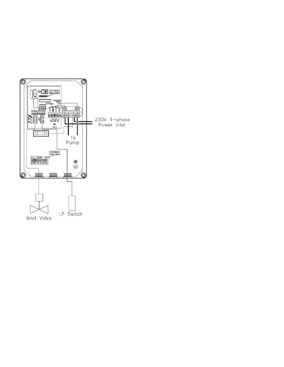
2. Wire the controller to a 230-volt single-phase breaker panel (see
figure 2).
D. Startup
1. Verify that the pretreatment equipment is installed and working
properly. Verify that no free chlorine is present in the feed water.
2. Verify that the on/off switch is in the off position.
3. Install a 10" five micron filter cartridge in the prefilter housing.
(Figure #1 item H)
4. Open the reject control valve completely (Figure # 1 item B) by
turning it counterclockwise.
5. Close the reject recycle control valve completely by turning it
clockwise.
6. Open the feed water shutoff valve installed in step III-B-1 above.
7. Manually open the inlet solenoid valve (figure #1 item I) by turn-
ing the white lever located near the valve outlet.
8. Water will flow through the system and to drain through the
reject flow meter (figure # 1 item F).
9. Manually close the inlet solenoid valve after the air has been
purged from the system, or after 10 minutes, whichever occurs
first.
10. Open the reject recycle valve two turns.
11. Move the controller on/off switch to the on position.
12. Adjust the reject control valves (figure # 1 items B & C) until the
desired flows are achieved. Closing the reject valve increases
the product flow and decreases the reject flow. Opening the
reject recycle valve decreases both the reject and product flow.
See the flow rate guidelines and temperature correction table in
the appendix to determine the flow rates for different operating
temperatures.
13. Allow the product water to flow to drain for 30 minutes.
14. Turn off the system and connect the product line to the point of
use. (Figure # 1 item G) The product water line should never be
restricted. Membrane and/or system damage may occur if the
product line is blocked.
15. Restart the system and record the initial operating data using the
log sheet in the next section.
E. Controller
1. When the power switch is turned on the pump will run as long
as the circuit between the tank level terminals and the interlock
terminals are closed.
2. To install a tank level switch, remove the jumpers from the termi-
nal strip and connect the level switch to the terminals. A small
plastic lever is installed in one of the terminals. This lever can be
moved to each terminal to open the contacts. The RO pump
and inlet valve will turn on when the level switch contacts are
closed (tank not full). The RO pump and inlet valve will turn off if
the level switch contacts open (tank full).
3. A pretreatment interlock switch can be installed in the same way
as the tank level switch.
4. If the pump suction pressure drops below the pressure switch
set point ( 5 – 8 psi) for five (5) seconds, the RO pump and
inlet valve will turn off. A red light on the front of the controller
will turn on to indicate that the unit has shutdown due to low
pressure. Turn the controller off and back on to reset the unit.
The controller is factory set to restart after a 20-minute delay.
The delay time can be changed by moving the jumper cap to
another position (see figure 2).
Figure 2
Figure 2
PWR 4011 Controller