Ii. controls, indicators, and components, Iii. operation, A. installation – Watts PWR4011 User Manual
Page 3: B. plumbing connections
3
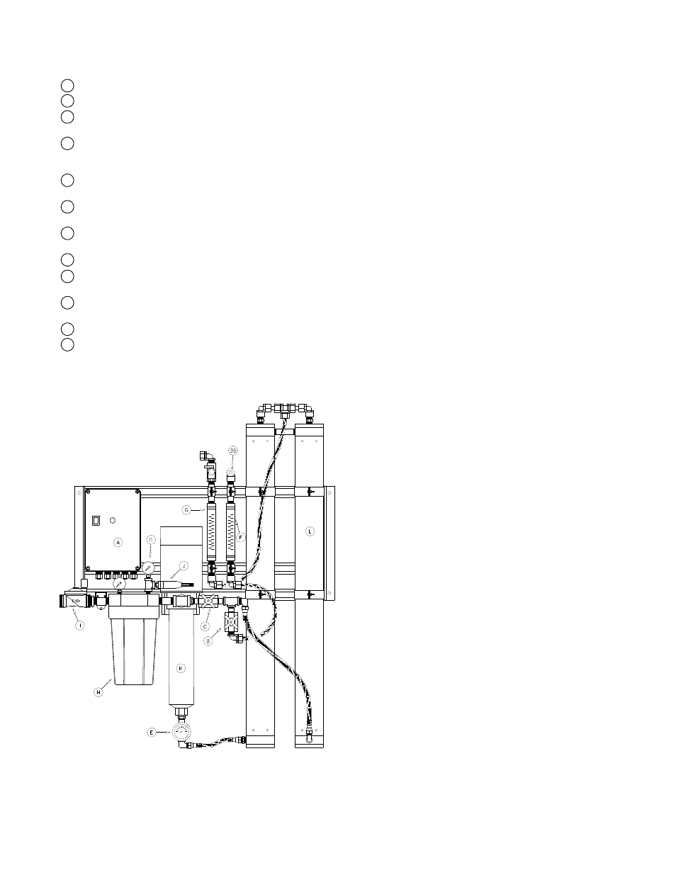
Figure 1
II. Controls, Indicators, and
Components
(See Figure 1)
A. Controller - Controls the operation of the system.
B. Reject Control Valve - Controls the amount of reject flow.
C. Reject Recycle Control Valve – Controls the amount of recycle
flow.
D. Prefilter Pressure Gauges - Indicates the inlet and outlet pres-
sure of the prefilter. The difference between these two gauges is
the prefilter differential pressure.
E. Pump Discharge Pressure Gauge - Indicates the pump dis-
charge pressure.
F. Reject Flow Meter - Indicates the reject flow rate in gallons per
minute (gpm).
G. Product Flow Meter - Indicates the product flow rate in gallons
per minute (gpm).
H. Prefilter Housing - Contains the RO prefilter.
I. Automatic Inlet Valve - Opens when pump is on and closes
when the pump is off.
J. Low Pressure Switch - Sends a signal to the controller if the
pump suction pressure is low.
K. RO Feed Pump - Pressurizes the RO feed water.
L. RO Membrane Vessels - Contains the RO membranes.
III. Operation
A. Installation
1. The water supply should be sufficient to provide a minimum of
20 psig pressure at the design feed flow.
2. Proper pretreatment must be determined and installed prior to
the RO system.
3. A fused high voltage disconnect switch located within 10 feet of
the unit is recommended. This disconnect is not provided with
the RO system.
4. Responsibility for meeting local electrical and plumbing codes
lies with the owner / operator.
5. Install indoors in an area protected from freezing. Space al-
lowances for the removal of the membranes from the pressure
vessels should be provided.
B. Plumbing Connections
Note: It is the responsibility of the end user to ensure that the
installation is done according to local codes and regulations.
1. Connect the pretreated feed water line to the inlet valve (Figure #
1 item I). A feed water shutoff valve should be located within 10
feet of the system.
2. Temporarily connect the outlet of the product water flow meter
to drain. (Figure # 1 item G) The product water line should
never be restricted. Membrane and/or system damage may
occur if the product line is blocked.
3. Connect the outlet of the reject water flow meter to a drain.
(Figure # 1 item F) The reject drain line should never be re-
stricted. Membrane and/or system damage may occur if the
reject drain line is blocked. An air gap must be located between
the end of the drain line and the drain. The use of a standpipe or
other open drain satisfies most state and local codes and allows
for visual inspection and sampling.