Drill hole and connect, Black tube from faucet to the drain saddle, Green tube connection – Watts PWRO4 User Manual
Page 6: Reverse osmosis module mounting, Tube connection (from faucet), Tank tee installation, Check air pressure in the tank, Step 5 step 6, Step 7, Step 8
6
Drill hole and Connect
3
⁄
8
" Black Tube
from Faucet to the Drain Saddle
IMPORTANT: The black
3
⁄
8
" drain tube must be as SHORT and
STRAIGHT as possible to the drain saddle, making a downward
slope from faucet to drain saddle to allow for proper drainage.
This is a gravity fed line and if there is any bend or dip in the
tube, the rinse water will not flow into the drain properly. Water
may back up and come out the air gap hole in the back of the
faucet.
Step A – With the drain saddle secured
onto the drain pipe, using a
1
⁄
4
"
drill bit installed in your electric
drill, insert the drill bit through
the opening in the drain saddle
and drill through the drain pipe .
Caution: It is very important to keep the drill centered to pre-
vent damage of the drain saddle while drilling.
Step B – Measure the
3
⁄
8
" black tube
from faucet to the drain saddle
on the drain pipe and make
a straight cut to the correct
length .
Step C – Slip black tube through black
compression nut . Insert black
tube into the opening in the
drain saddle and hand tighten the black nut, and add
1
⁄
4
turn with a wrench .
STEP 5
STEP 6
Green Tube Connection
Step A – Locate green tube attached to the
RO Module . Insert the open end of
the green
1
⁄
4
" tube into the open
1
⁄
4
"
Quick-Connect fitting on the Adapt-
A-Valve™ making sure the tube is
pushed in all the way to the tube
stop .
Step B – Connect the green tube from the RO
module to the Adapt-A-Valve™ that
is connected to the angle stop valve .
Leave enough tube so it is not kinked and cut the tube to
the desired length .
STEP 7
Reverse Osmosis Module Mounting
Step A – Determine best location for the
RO module to be mounted to
allow for future system main-
tenance . The parts bag has 2
self-tapping screws . Using an
electric drill with a Phillips bit,
screw them into the cabinet
wall 6" apart and 16" from the
bottom of the cabinet .
Note: Do not cut any RO system tubes at this time
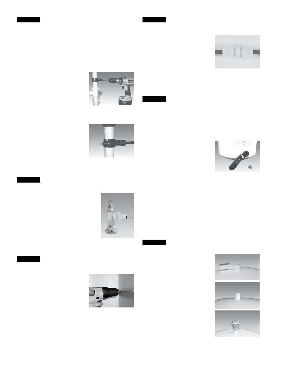
STEP 8
Red
1
⁄
4
" Tube Connection (from faucet)
Step A – Using the white plastic union
found in the parts bag, deter-
mine where the
1
⁄
4
" red tubing
from the faucet and the
1
⁄
4
" red
tubing from the RO membrane
housing would join together
comfortably . Cut red tube from
RO faucet to length leaving a
straight cut edge . Insert the red tube from RO faucet in one
end of the white plastic union and the red tube from RO
membrane housing in the other end . Use a
5
⁄
8
" wrench to
tighten both of the white plastic nuts securely .
STEP 10
Tank Tee Installation
Step A – Wrap (7 to 12 turns) of Teflon
®
tape clockwise around the
male pipe threads (MPT) on the
Stainless Steel fitting on top of
the tank .
NOTE: Do not let the tape cover the
opening.
Step B – Thread the plastic elbow (sup-
plied in the parts bag) onto the
stainless steel connection on
the top of tank . Tighten using
an adjustable wrench. Do not
over tighten as plastic could
crack .
STEP 9
Check Air Pressure in the Tank
Note: Check air pressure when tank is empty of water!
Check air pressure in the storage tank when you notice a de-
crease in available water from the RO system. Air can be added
with a bicycle pump using the schrader valve that is located on
the lower side of the tank behind the blue plastic cap.
Step A – Turn off the incoming water
supply to the RO by turning the
knob on the Adapt-A-Valve™
clockwise until it stops . (Follow
the green tube away from the
RO system to find the Adapt-A-
Valve™ .)
Step B – Open the RO Faucet and allow water to drain from the tank
until it is completely empty .
Tip: When water from the RO faucet slows to a trickle with the
faucet still in the open position, you may add air to the tank to
purge any left over water. This will ensure that the tank is com-
pletely empty.
Step C – Once all water in the tank is purged, check air pressure us-
ing an air pressure gauge . It should read between 5 - 7psi .
(Digital air pressure gauge is recommended)
Step D – Follow startup procedure on Page 7 .
Teflon
®
is a registered trademark of E .I . Dupont de Nemours & Company .