Adapt-a-valve™ installation, Configuration for, Configuration – Watts PWRO4 User Manual
Page 5: Drain saddle tube connection, Step 3, Step 4
5
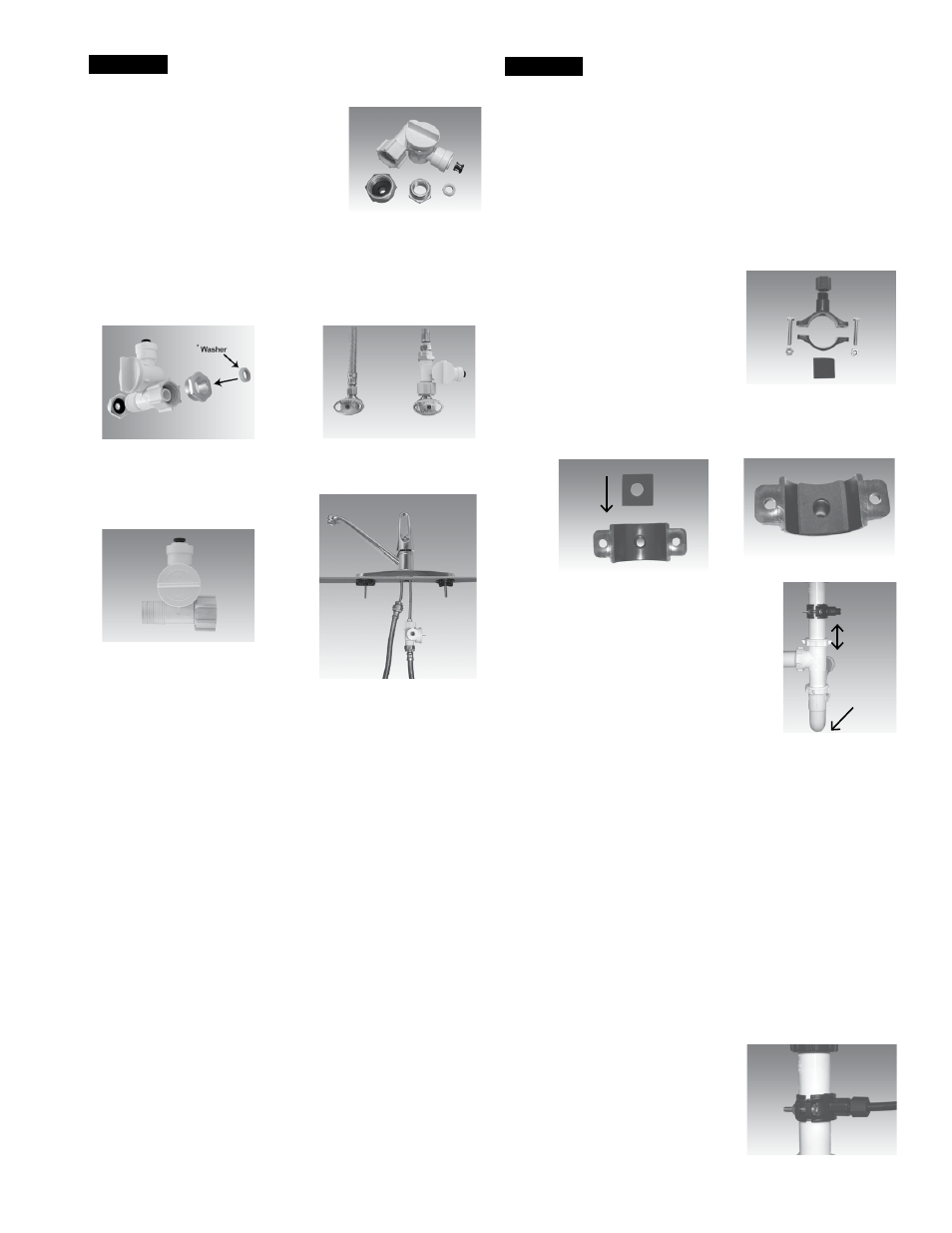
Adapt-A-Valve™ Installation
Verify contents prior to installation:
( 1 ) - Plastic Adapt-a-Valve™ & Black Collet
( 1 ) - Brass Adapter no washer
( 1 ) - Brass Adapter with black washer
( 1 ) - White rubber washer
Water supply line to the system must be from the cold water
supply line only. Hot water will severely damage your system.
WARNING: Do not use Teflon tape with the Adapt-A-Valve™.
For
3
⁄
8
" Configuration
For
1
⁄
2
" Configuration
Step A - Turn off the cold water supply to the faucet by turning the
angle stop valve completely off .
Step B - Open cold water sink faucet to relieve pressure .
Step C - Choosing the configuration that fits your plumbing, at-
tach the Adapt-A-Valve™ as illustrated in the four photos
above .
STEP 3
Hot
Supply
Cold
Supply
Hot
Supply
Cold
Supply
(With Brass Fittings)
* Insert White Washer
(Without Brass Fittings)
1
⁄
2
" Configuration
Drain Saddle Installation -
Fits standard 1¼" – 1½" drain pipes
Follow all local plumbing codes for your installation.
Caution: If you have a garbage disposal, do not install the drain
saddle near it. Installation of the drain saddle must be either
above the garbage disposal, or if a second sink drain is avail-
able, install it above the cross bar on the second drain. Installa-
tion of the drain saddle near a garbage disposal may cause the
drain line to plug.
Step A – Locate the drain saddle kit in the parts bag .
Gather the pieces of the drain saddle
( 1 ) - Black compression nut
( 1 ) - Semicircle bracket with opening
( 2 ) - Screws
( 1 ) - Foam gasket
( 2 ) - Nuts for screws
( 1 ) - Semicircle bracket
Step B – The small square black foam gasket with a circle cut out
of the middle must be applied to the inside of the drain
saddle . Remove sticky tape backing and stick to the drain
saddle as shown .
Step C – The drain saddle must be installed
at least 1 ½" above the nut of the
P-Trap elbow or cross bar from the
garbage disposal to insure proper
drainage . Using the 1/4" drill bit,
drill into the drain pipe at best avail-
able location as specified above,
for drain saddle installation . Take
extreme caution to only drill through
one side of the drain pipe .
Step D – Assemble the drain saddle around the drain pipe and align
drain saddle fitting opening with the hole drilled in the
previous step - you may use a small screwdriver to feed
through the drain saddle into the drain pipe to aid with the
alignment . Using a Phillips screw driver tighten the drain
saddle bolts evenly and securely on both sides .
Caution: Do not over tighten the screws. It may crack the drain
saddle.
Drain Saddle Tube Connection
The black 3/8" drain tube must be as SHORT and STRAIGHT as
possible to the drain saddle, making a downward slope from faucet
to drain saddle to allow for proper drainage . This is a gravity fed line
and if there is any bend or dip in the tube, the rinse water will not
flow into the drain properly . Water may back up and come out the air
gap hole in the back of the faucet .
Step A – Measure the 3/8" drain tube from faucet to the drain saddle
on the drain pipe and make a straight cut to the correct
length .
Step B – Slip drain tube through black
compression nut . Insert drain
tube into the opening in the
drain saddle and hand tighten
the black nut, and add 1/4 turn
with a wrench .
STEP 4
1.5"
P-Trap
Elbow