Dimensions, Setup for alternate operation – Banner K80L Segmented EZ-LIGHT User Manual
Page 3
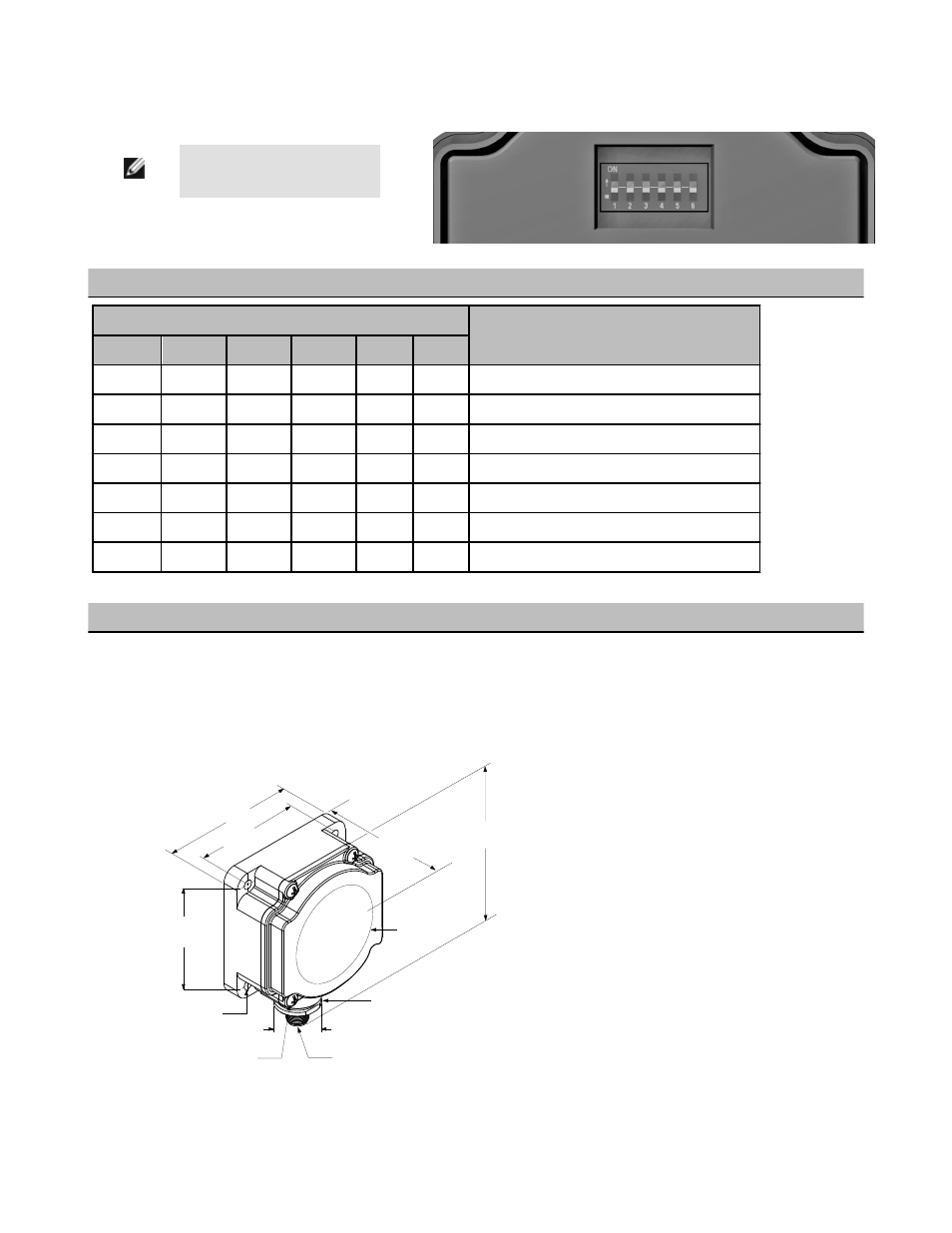
Setup for Alternate Operation
NOTE: The Program DIP switch
is located inside the K80L cover.
Remove the four screws to remove the cover.
Configuration for Flash function (1-color models only)
DIP Switch Positions
LED Function
SW1
SW2
SW3
SW4
SW5
SW6
OFF
OFF
OFF
OFF
OFF
OFF
Color 1 ON solid
ON
OFF
OFF
OFF
OFF
OFF
Color 1 Flashes – 50% duty cycle; 2 Hz rate
OFF
ON
OFF
OFF
OFF
OFF
Color 1 Flashes – 50% duty cycle; 1 Hz rate
OFF
OFF
ON
OFF
OFF
OFF
Color 1 Flashes – 50% duty cycle; 0.5 Hz rate
OFF
OFF
OFF
ON
OFF
OFF
Color 1 Flashes – 25% duty cycle; 1 Hz rate
OFF
OFF
OFF
OFF
ON
OFF
Color 1 Flashes – 25% duty cycle; 0.5 Hz rate
OFF
OFF
OFF
OFF
OFF
ON
Color 1 Flashes – 25% duty cycle; 0.25 Hz rate
Configuration for Demo mode (2-, 3-, and 4-color models only)
Change the switch 1 position to ON.
The individual sectors will light depending on the input
power, as described at right:
Black wire input: Colors 1 and 2 alternate
Brown wire input: Colors light simultaneously
White wire input: Colors light in rotation (3- and 4-color models only
Dimensions
109.5 mm
(4.31")
80.8 mm
(3.18")
41.0 mm
(1.61")
Ø 66.0 mm
(2.69")
26.0 mm
(1.02")
M12 X 1
65.0 mm
(2.56")
65.0 mm
(2.56")
4X 8–32 UNC
Max. Torque 1.12 Nm (10 in–lbf)
4X Ø 5.5 mm (Ø 0.22")
Max. Torque 1.12 Nm (10 in–lbf)
with supplied screws
Internal Threads ½ - 14 NPSM
Max. Torque 2.25 Nm (20 in–lbf)
EZ-LIGHT® K80L Segmented Indicator
P/N 132728 rev. D
www.bannerengineering.com - tel: 763-544-3164
3