World-beam, Qs30 – dc voltage, Fixed-field mode overview – Banner WORLD-BEAM QS30 Series User Manual
Page 2: Sensor setup, Fixed-field sensing – theory of operation, Sensing reliability, Background reflectivity and placement
WORLD-BEAM
®
QS30 – DC Voltage
2
P/N 119165 rev. A
Banner Engineering Corp.
•
Minneapolis, MN U.S.A.
www.bannerengineering.com • Tel: 763.544.3164
Fixed-Field Mode Overview
QS30 Series self-contained fixed-field sensors are small, powerful, visible red diffuse
mode sensors with far-limit cutoff (a type of background suppression). Their high
excess gain and fixed-field technology allow them to detect objects of low reflectivity
that are directly in front of another surface, while ignoring the surface in the
background.
The cutoff distance is fixed. Backgrounds and background objects must always be
placed beyond the cutoff distance.
Fixed-Field Sensing – Theory of Operation
In operation, the QS30FF compares the reflections of its emitted light beam (E) from an
object back to the sensor’s two differently-aimed detectors R1 and R2 (see Figure 2). If
the near detector (R1) light signal is stronger than the far detector (R2) light signal (see
object A, closer than the cutoff distance), the sensor responds to the object. If the far
detector (R2) light signal is stronger than the near detector (R1) light signal (see object
B, object beyond the cutoff distance), the sensor ignores the object.
The cutoff distance for model QS30FF sensors is fixed at 200, 400 or 600 millimeters
(8", 16", or 24"). Objects lying beyond the cutoff distance are ignored, even if they are
highly reflective. However, it is possible to falsely detect a background object, under
certain conditions (see Background Reflectivity and Placement).
In the drawings and discussion on these pages, the letters E, R1, and R2 identify how
the sensor’s three optical elements (Emitter “E”, Near Detector “R1”, and Far Detector
“R2”) line up across the face of the sensor. The location of these elements defines the
sensing axis (see Figure 2). The sensing axis becomes important in certain situations,
such as those illustrated in Figures 5 and 6.
Sensor Setup
Sensing Reliability
For best sensing reliability, the sensor-to-object distance should be positioned to
maximize excess gain. The excess gain curves for these products are shown on page
5. Sensing at higher excess gains will make maximum use of each sensor’s available
sensing power. The background must be placed beyond the cutoff distance; more
reflective backgrounds must be placed further back. Following these two guidelines will
improve sensing reliability.
Background Reflectivity and Placement
Avoid mirror-like backgrounds that produce specular reflections. False sensor response
will occur if a background surface reflects the sensor’s light more strongly to the
near detector, or “sensing” detector (R1) than to the far detector, or “cutoff” detector
(R2). The result is a false ON condition (Figure 3). Use of a diffusely-reflective (matte)
background will cure this problem. Other possible solutions are to angle the sensor or
angle the background (in any plane) so the background does not reflect light back to
the sensor (see Figure 4). Position the background as far beyond the cutoff distance as
possible.
An object beyond the cutoff distance, either stationary (and when positioned as shown
in Figure 5), or if it moves past the face of the sensor in a direction perpendicular to the
sensing axis, can cause unwanted triggering of the sensor if it reflects more light to the
near detector than to the far detector. The problem is easily remedied by rotating the
sensor 90° (Figure 6). The object then reflects the R1 and R2 fields equally, resulting in
no false triggering. A better solution, if possible, may be to reposition the object or the
sensor.
Sensing
Axis
R1
R2
E
As a general rule, the most reliable sensing
of an object approaching from the side
occurs when the line of approach is
parallel to the sensing axis.
Figure 2. Fixed-field sensing axis
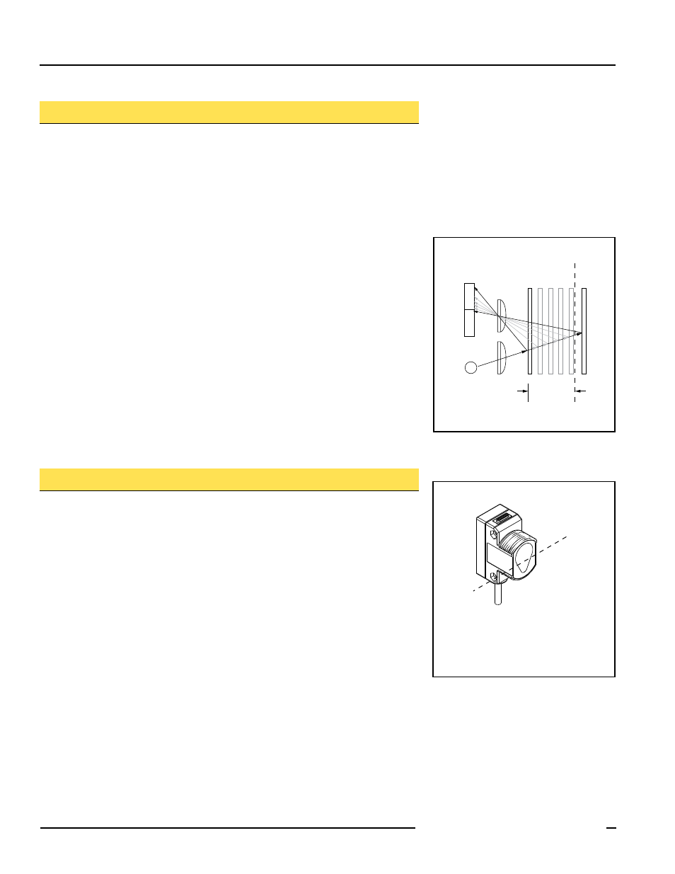
R1
R2
Lenses
Object
A
Object B
or
Background
Sensing
Range
Cutoff
Distance
E
Receiver
Elements
Near
Detector
Far
Detector
Emitter
Object is sensed if amount of light at R1
is greater than the amount of light at R2
Figure 1. Fixed-field concept