Banner S18 Series User Manual
Page 6
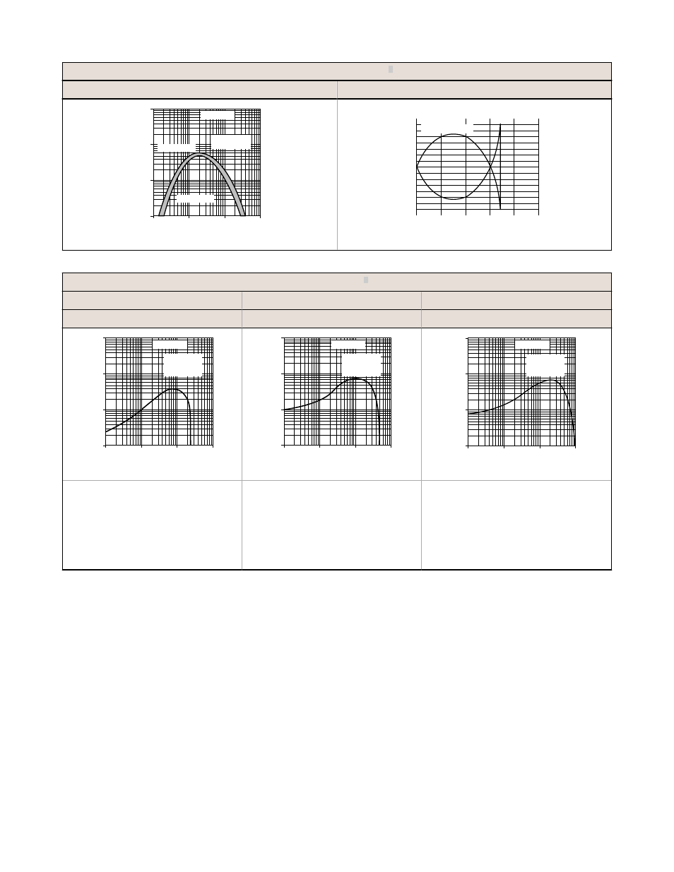
Diffuse 300 mm Mode
3
Excess Gain
Beam Pattern
1
10
100
10 mm
(0.4")
100 mm
(4")
1000 mm
(40")
1 mm
(0.04")
1000
E
X
C
E
S
S
G
A
I
N
DISTANCE
S18 Series
Long Range
Diffuse Mode
Maximum Gain
Minimum Gain
400 mm
(15")
320 mm
(12")
240 mm
(9")
160 mm
(6")
80 mm
(3")
0
0
5 mm
10 mm
15 mm
5 mm
10 mm
15 mm
0
0.2"
0.4"
0.6"
0.2"
0.4"
0.6"
DISTANCE
S18 Series
Long Range Diffuse
Fixed-Field
3
25 mm Mode
50 mm Mode
100 mm Mode
Excess Gain
Excess Gain
Excess Gain
1
10
100
1 mm
(0.04")
10 mm
(0.4")
100 mm
(4")
0.1 mm
(0.004")
E
X
C
E
S
S
G
A
I
N
DISTANCE
1000
S18 Series
Fixed-field mode
with 25 mm far
limit cutoff
1
10
100
1 mm
(0.04")
10 mm
(0.4")
100 mm
(4")
0.1 mm
(0.004")
E
X
C
E
S
S
G
A
I
N
DISTANCE
1000
S18 Series
Fixed-field mode
with 50 mm far
limit cutoff
1
10
100
1 mm
(0.04")
10 mm
(0.4")
100 mm
(4")
0.1 mm
(0.004")
E
X
C
E
S
S
G
A
I
N
DISTANCE
1000
S18 Series
Fixed-field mode
with 100 mm far
limit cutoff
Using 18% gray test card: Cutoff
distance will be 95% of value shown.
Using 6% black test card: Cutoff
distance will be 90% of value shown.
Ø 10 mm spot size @ 8 mm focus
Ø 10 mm spot size @ 25 mm cutoff
Using 18% gray test card: Cutoff
distance will be 90% of value shown.
Using 6% black test card: Cutoff
distance will be 85% of value shown.
Ø 10 mm spot size @ 10 mm focus
Ø 10 mm spot size @ 50 mm cutoff
Using 18% gray test card: Cutoff
distance will be 85% of value shown.
Using 6% black test card: Cutoff
distance will be 75% of value shown.
Ø 10 mm spot size @ 20 mm focus
Ø 10 mm spot size @ 100 mm cutoff
Focus and spot sizes are typical.
S18 Sensors (DC-Voltage Series)
6
www.bannerengineering.com - tel: 763-544-3164
P/N 121522 Rev. B