Fixed-field mode overview, Sensor setup – Banner S18 Series User Manual
Page 2
Fixed-Field Mode Overview
S18 Series self-contained fixed-field sensors are small, powerful, infrared diffuse mode sensors with far-limit cutoff (a type
of background suppression). Their high excess gain and fixed-field technology allow them to detect objects of low
reflectivity, while ignoring background surfaces.
The cutoff distance is fixed. Backgrounds and background objects must always be placed beyond the cutoff distance.
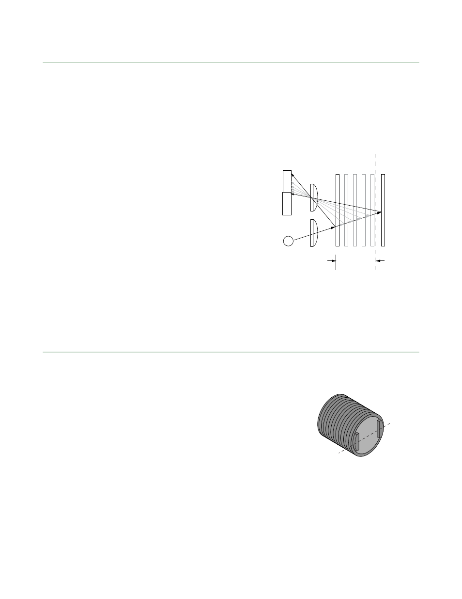
Fixed-Field Sensing – Theory of Operation
The S18FF compares the reflections of its emitted light beam (E)
from an object back to the sensor’s two differently aimed detectors,
R1 and R2. If the near detector (R1) light signal is stronger than the
far detector (R2) light signal (see object A, closer than the cutoff
distance), the sensor responds to the object. If the far detector (R2)
light signal is stronger than the near detector (R1) light signal (see
object B, beyond the cutoff distance), the sensor ignores the object.
The cutoff distance for model S18FF sensors is fixed at 25, 50 or 100
millimeters (1", 2", or 4"). Objects lying beyond the cutoff distance
usually are ignored, even if they are highly reflective. However, it is
possible to falsely detect a background object, under certain
conditions (see Background Reflectivity and Placement).
In the drawings and discussion on these pages, the letters E, R1, and
R2 identify how the sensor’s three optical elements (Emitter “E”,
Near Detector “R1”, and Far Detector “R2”) line up across the face of
the sensor. The location of these elements defines the sensing axis
on page 2). The sensing axis becomes important in
certain situations, such as those illustrated in
on page 3
and
on page 3.
R1
R2
Lenses
Object
A
Object B
or
Background
Sensing
Range
Cutoff
Distance
E
Receiver
Elements
Near
Detector
Far
Detector
Emitter
Object is sensed if amount of light at R1
is greater than the amount of light at R2
Figure 1. Fixed-field concept
Sensor Setup
Sensing Reliability
As a general rule, the most reliable sensing of an object approaching from the
side occurs when the line of approach is parallel to the sensing axis.
For highest sensitivity, position the target object for sensing at or near the
point of maximum excess gain. The excess gain curves for these products are
shown on page 5. Maximum excess gain for the 25 mm models occurs at a
lens-to-object distance of about 7 mm; for 50 mm models, at about 10 mm;
and for the 100 mm models, at about 20 mm. Sensing at or near this
distance will make maximum use of each sensor’s available sensing power.
The background must be placed beyond the cutoff distance. (Note that the
reflectivity of the background surface also may affect the cutoff distance.)
Following these two guidelines will improve sensing reliability.
Sensing
Axis
R2
R1
E
Figure 2. Fixed-field sensing axis
Background Reflectivity and Placement
Avoid mirror-like backgrounds that produce specular reflections. False sensor response will occur if a background surface
reflects the sensor’s light more strongly to the near detector, or “sensing” detector (R1), than to the far detector, or
“cutoff” detector (R2). The result is a false ON condition (see
on page 3). To cure this problem, use a diffusely
S18 Sensors (DC-Voltage Series)
2
www.bannerengineering.com - tel: 763-544-3164
P/N 121522 Rev. B