Q60laf series laser adjustable-field sensors, Setting the cutoff distance, Sensing reliabilty – Banner Q60 Background Suppression Series User Manual
Page 4: Background reflectivity and placement
Q60LAF Series Laser Adjustable-Field Sensors
4
P/N 114348
Banner Engineering Corp.
•
Minneapolis MN, U.S.A.
www.bannerengineering.com • Tel: 763.544.3164
Setting the Cutoff Distance
The cutoff distance for Q60LAF sensors may be adjusted between 200 mm and
1400 mm (8" to 55") for Class 1 laser models, and between 200 mm and 2000 mm
(8" to 80") for Class 2 laser models.
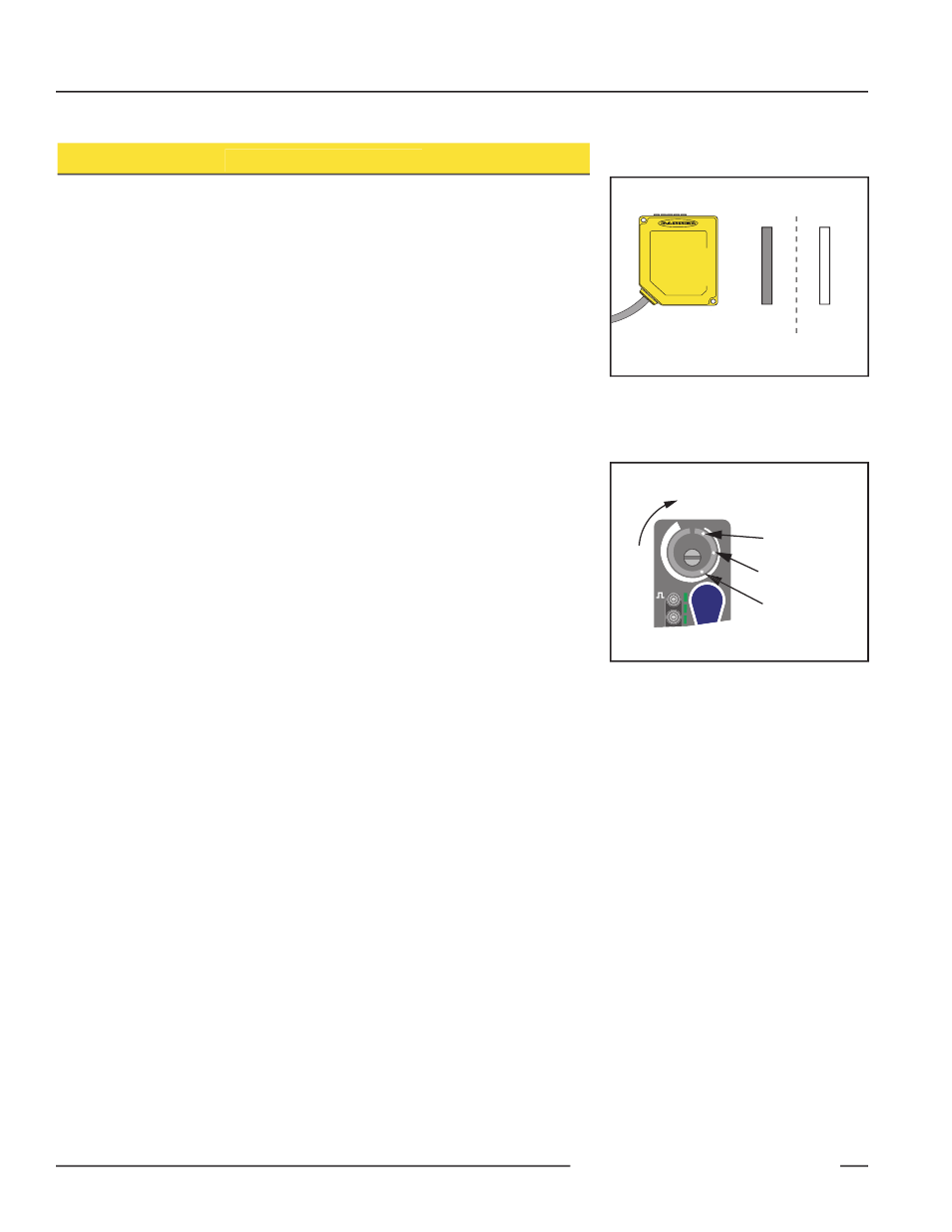
To maximize contrast, position the lightest possible background to be used, at the
closest position it will come to the sensor during use (Figure 5). Using a small
screwdriver in the adjustment screw, adjust the cutoff distance until the threshold
is reached and the green Light Sensed indicator changes state. (If the indicator
never comes ON, the background is beyond the maximum sensing cutoff and will be
ignored.) Note the position of the rotating cutoff position indicator at this position.
Then repeat the procedure, using the darkest target, placed in its most distant
position for sensing. Adjust the cutoff so that the indicator is midway between the two
positions (Figure 6).
NOTE: Setting the cutoff distance adjustment screw to its maximum clockwise
position places the receiver lens directly in front of the receiver elements and
results in the Q60 performing as a long-range diffuse sensor.
Sensing Reliabilty
For highest sensitivity, the sensor should be mounted so that the target object will be
sensed at or near the point of maximum excess gain. The excess gain curves on page
1 show excess gain vs. sensing distance for 200 mm, 1,200 mm and 2 m cutoffs.
Maximum excess gain for a 200 mm cutoff occurs at a lens-to-object distance of
about 150 mm, and for a 2 m cutoff, at about 500 mm. The background must be
placed beyond the cutoff distance. Following these two guidelines makes it possible to
detect objects of low reflectivity, even against close-in re flec tive back grounds.
Background Reflectivity and Placement
Avoid mirror-like backgrounds that produce specular reflections. False sensor
re sponse will occur if a back ground surface reflects the sensor’s light more strongly
to the near detector (R1) than to the far detector (R2). The result is a false ON
condition (Figure 7). Use of a diffusely-reflective (matte) background will cure this
problem. Other possible solutions are to angle either the sensor or the background (in
any plane) so that the back ground does not reflect back to the sensor.
An object beyond the cutoff distance, either moving or stationary (and when
po si tioned as shown in Figure 8), can cause unwanted triggering of the sensor
because it reflects more light to the near detector than to the far detector. The
problem is easily rem e died by rotating the sensor 90° to align the sensing axis
horizontally. The object then reflects the R1 and R2 fields equally, resulting in no false
triggering.
Target
Background
Cutoff
Distance
E
R2
R1
ON
DELAY
DELAY
DO
SIG
LO
RANGE
In
cr
ea
si
ng
Di
sta
nce
Set Cutoff Midway
Between
Farthest Target Object
Closest Background
Figure 6. Setting the cutoff distance
Figure 5. Set cutoff distance approximately
midway between the farthest
target and the closest background