45lm series modules, Removing and installing the plug-in modules, Warning – Banner Q45 Laser DC Series User Manual
Page 4
Removing and Installing the Plug-In Modules
To remove or install any of the 45LM modules (done through the top of the sensor),
perform the following steps:
1)
Remove all power from the sensor and load.
2)
Loosen the top cover hold-down screw and raise the transparent cover
(it is hinged).
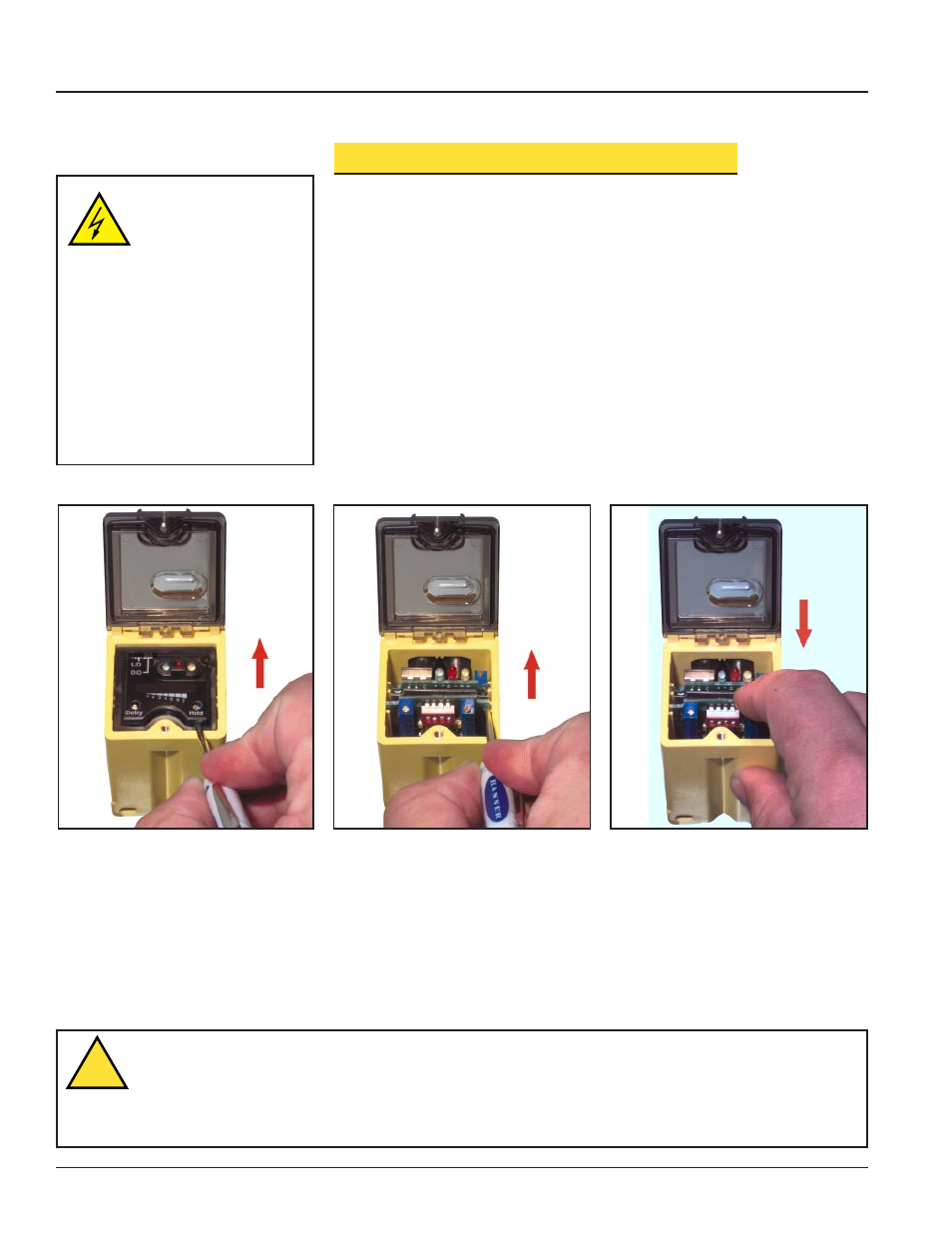
3)
Insert a small screwdriver into one of the slots at the front of the black inner
cover, lift and remove (Figure 5).
4)
Insert a small screwdriver into one of the slots at the side of the module to be
removed and pry it up until you can grasp it with your fingers and remove
(Figure 6).
5)
Press the new module into place (Figure 7).
6) Replace the black cover, then the transparent hinged cover, and tighten the
hold-down screw.
7)
Reapply power as desired.
NOTE: If only installing a new module (and not removing an old one), skip step 4.
Banner Engineering Corp., 9714 Tenth Ave. No., Minneapolis, MN 55441 • Phone: (612) 544-3164 • FAX (612) 544-3213 • E-mail: [email protected]
45LM Series Modules
Figure 5. Insert a small screwdriver into
the slot and lift the black cover
to remove.
Figure 6. Using the small screwdriver in
the module slot if necessary to
nudge the module loose, lift the
module up and out.
Figure 7. Slide the new module into place,
pressing until it fits snugly.
CAUTION . . . Electrical
Shock Hazard
An electrical shock hazard
exists inside the sensor
whenever power is applied.
Remove all power to the sensor (and to
the load) whenever the transparent top
cover will be raised and the black inside
cover will be removed.
Failure to remove power while these covers
are removed could result in injury.
NOTE: It is not necessary to remove power
simply to adjust the Sensitivity or
Timing controls, as long as the
black inside cover remains in place.
WARNING . . .
Not To Be Used for Personnel Protection
Never use these products as sensing devices for personnel protection. Doing so could lead to serious injury or death.
These sensors do NOT include the self-checking redundant circuitry necessary to allow their use in personnel safety
applications. A sensor failure or malfunction can cause either an energized or de-energized sensor output condition. Consult your current
Banner Safety Products catalog for safety products which meet OSHA, ANSI and IEC standards for personnel protection.
!