45lm series modules, Measuring excess gain and contrast – Banner Q45 Laser DC Series User Manual
Page 3
45LM Series Modules
page
3
Measuring Excess Gain and Contrast
The Q45’s optional seven-element LED array may be used to measure the excess gain
and contrast in any sensing situation and during sensor installation and maintenance.
Excess gain is a measurement of the amount of light energy falling on the receiver of
a photoelectric sensor
over and above the minimum amount necessary to operate the
sensor’s amplifier. Excess gain is expressed as a ratio:
Excess gain (E.G.) = light energy falling on receiver
amplifier threshold
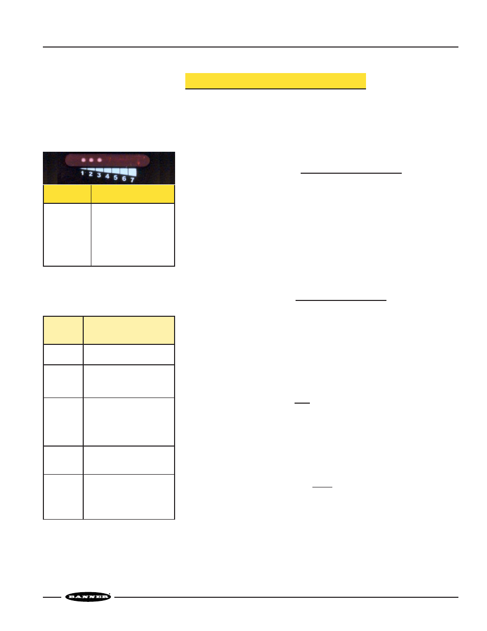
The amplifier threshold is the point at which the sensor’s output switches. The Q45’s
threshold corresponds to the #3 level of the LED array. That is, when LEDs #1
through #3 are lit, the excess gain of the received light signal is about “1x.”
The table at left (Figure 3) shows how excess gain relates to the LED array indicator.
Contrast is the ratio of the amount of light falling on the receiver in the “light” state as
compared to the “dark” state. Contrast is also referred to as “light-to-dark ratio.”
Optimizing the contrast in any sensing situation will increase the reliability of the
sensing system. Contrast may be calculated if excess gain values are known for both
the light and dark conditions:
Contrast
= Excess gain (light condition)
Excess gain (dark condition)
To determine the contrast for any sensing application, present both the “light” and
“dark” conditions to the Q45, and read the signal for each. Take the ratio of the two
numbers (from Figure 3) that correspond to the highest LED numbers registered for
the “light” and “dark” conditions.
For example, if LEDs #1 through #6 come ON in the “light” condition and LEDs #1
and #2 come ON in the “dark” condition, the contrast (referring to Figure 2) is
calculated as follows:
Contrast
=
6x = 12
0.5x
This value is expressed as “12:1” or “twelve-to-one.”
The best sensor adjustment will cause all seven LEDs to come ON for the “light”
condition, and will cause no LEDs to come ON in the “dark” condition. In this
situation (such as an application in which a box breaks the beam of an opposed mode
emitter and receiver):
Contrast is greater than
8x = 32:1
0.25x
Of course, it is not always possible to adjust a sensor to maintain this much contrast.
However, it is important to always adjust a sensor for the greatest amount of contrast
possible for any sensing situation. The LED signal strength indicator array makes this
easy. Figure 4 gives general guidelines for contrast values.
Figure 3. The 7-segment LED array and its
corresponding Excess Gain
Values
#1
#2
#3
#4
#5
#6
#7
0.25x
0.5x
1.0x
2.0x
4.0x
6.0x
8.0x
LED Number
Approximate Gain
10 or
greater
Contrast
Ratio
Recommendation
1.2 or less
Unreliable. Use an
alternative sensing scheme.
1.2 to 2
Poor contrast. Minor sensing
system variables will affect
sensing reliability.
2 to 3
Low contrast. Sensing
environment must remain
perfectly clean and all other
sensing variables must
remain stable.
3 to 10
Good contrast. Minor
sensing system variables will
not affect sensing reliability.
Excellent contrast. Sensing
should remain reliable as long
as the sensing system has
enough excess gain for
operation.
Figure 4. Contrast values and
corresponding guidelines