Installing the chemical-resistant models – Banner U-GAGE QT50U Ultrasonic Sensors User Manual
Page 6
Action
Result
Position the target at the desired midpoint for the sensing
window.
Click the TEACH button.
Output LED changes to flashing red
3. Teach the second limit.
Action
Result
Without moving the target, click the button again.
The sensor stores sensing window and the Output LED turns solid
amber. The sensor returns to Run mode.
Output OFF
Taught Position
(e.g., wall or floor)
Position
-100 mm
Position
+100 mm
Sensor
Output
ON
Sensor
Output
OFF
Any object in this area will switch the output,
whether or not the object returns a good signal to the sensor.
Sensing Range
200 mm
Output ON
Figure 7. An application for Auto-Window feature (retroreflective mode)
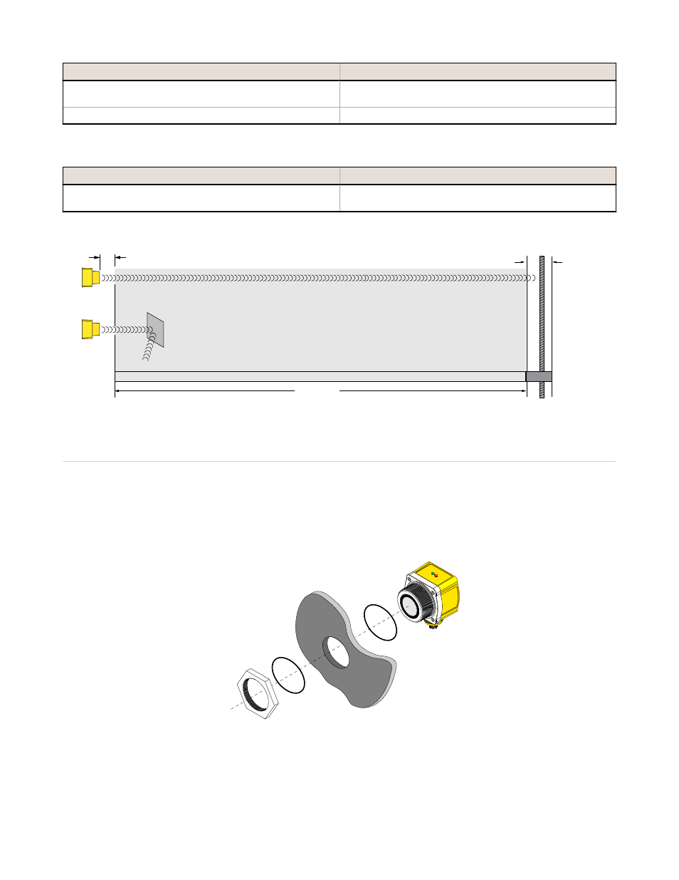
Installing the Chemical-Resistant Models
The sensor may be threaded directly into the side of a tank (see dimensions for hole diameter and thread specifications),
or into a non-threaded hole, using the included threaded nut. Recommended through-hole size: 56.5 ± 0.5 mm.
For a non-threaded hole, install an o-ring onto the flange, and insert the flange completely into the hole until the sensor
front surface is against the tank’s exterior surface. Place the other o-ring into the groove on the Teflon nut, and thread the
nut onto the flange. Tighten enough to eliminate gaps between the flange and the tank surface. This will ensure that the o-
rings are fully compressed.
QT50U Chemical-Resistant Sensor
Tank Section
O-Ring
O-Ring
Threaded Teflon
Nut (included)
Figure 8. Installing a chemical-resistant sensor model into a threaded hole in a tank
U-GAGE QT50UVR Series Sensors
6
www.bannerengineering.com - tel: 763-544-3164
P/N 117764 Rev. F