Sl series slot sensor, Overview, Sensitivity adjustment – Banner SL10 Series Slot Sensors User Manual
Page 2
Banner Engineering Corp. • Minneapolis, MN U.S.A
www.bannerengineering.com • Tel: 763.544.3164
2
P/N 58341I9B
SL Series Slot Sensor
Overview
The SL10 Series Slot Sensor (sometimes called a “Fork Sensor”) comprises an
opposed-mode emitter and its receiver inside a single convenient housing. Opposed-
mode sensing is very reliable, and the single self-contained housing provides easy
installation, with no sensor alignment required. In addition, the molded-in arrow on the
emitter portion of the housing and the slotted design on the receiver portion of the
housing show at a glance the position of the beam, simplifying installation placement.
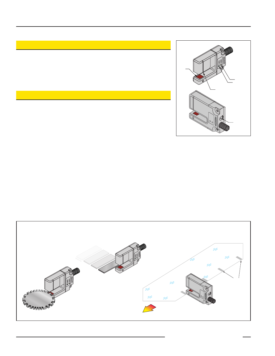
Figure 1. SL10 Series features
Sensitivity Adjustment
The sensor’s sensitivity is adjusted by turning the 4-turn clutched Sensitivity
potentiometer with a small slotted screwdriver. Apply power to the sensor and:
1. Set the potentiometer to minimum sensitivity (fully counter-clockwise, 4 full
turns or more) and present the Light condition. If the yellow Signal Condition
indicator is ON, that is your Light condition sensitivity position. If not, proceed
to step 2.
2. Turn the potentiometer clockwise, just until the yellow Signal Condition indicator
comes ON; note its position.
3. Present the Dark condition and turn the potentiometer clockwise, just until the yellow
Signal Condition indicator comes ON; note its position.
4. For maximum reliability, the difference between these two positions should be at
least one full turn. Set your sensitivity midway between the two positions for
best sensing results.
If the object to be sensed is very thin and non-metallic, the sensor may emit too much
light energy for the object to completely block the beam. To test this, place the object in
the sensing position, and decrease the sensitivity until the yellow LED goes OFF.
Remove the object; verify that the indicator comes ON solidly. If this does not occur,
investigate other sensing alternatives.
Receiver (Beam Aligns at Groove)
Power ON LED
Signal LED
Emitter
Sensitivity
Adjustment
Figure 2. SL10 Series typical applications
Gear Tooth Detection
Edge Detection
Packaging Film
Register Marks
Register Mark Detection
on Clear Film