Overview, Alignment indicating device – Banner Q45 Series User Manual
Page 6
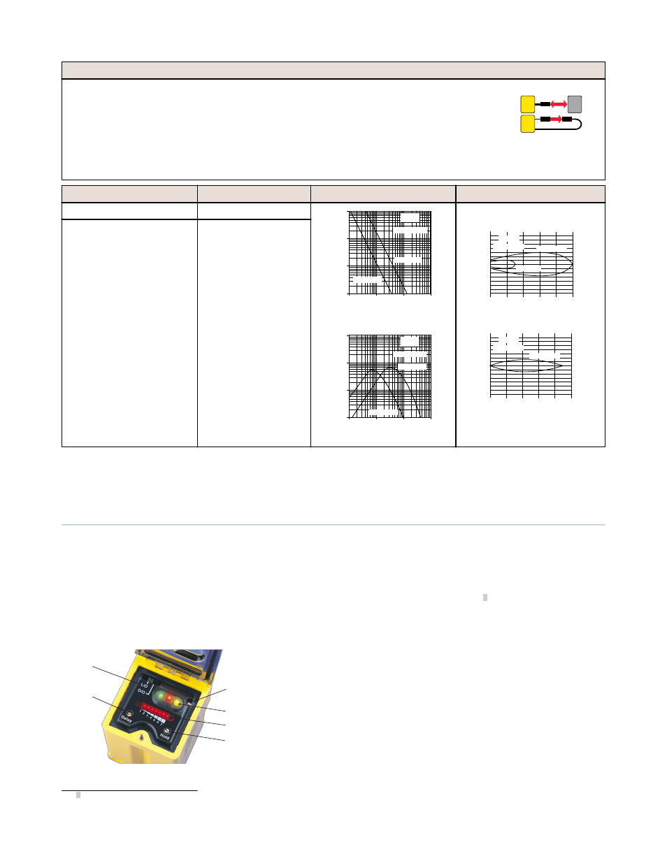
Plastic Fiber Optic Models
Lower in cost than glass fiber optics, plastic fiber optics are ideal for use in situations where environmental
conditions allow (for example, low levels of acids, alkalis, and solvents). Most are easily cut to length in the
field, and are available in a variety of sensing end styles. For more information on compatible plastic fiber
optics, refer to your current catalog.
Diffuse mode performance curves are based on a 90% reflectance white test card.
Range: Range varies by sensing mode and fiber optics used.
Output Type: SPDT Electro-mechanical relay
PLASTIC FIBER
Visible red, 660 nm
Models
Cable
Excess Gain
Beam Pattern
Q45VR2FP
5-wire 2 m (6.5 ft) cable
1
10
100
10 mm
0.4 in
100 mm
4.0 in
1000 mm
40 in
1 mm
0.04 in
1000
E
X
C
E
S
S
G
A
I
N
DISTANCE
Q45FP
Opposed Mode
PIT46U Fibers
PIT26U Fibers
1
10
100
1 mm
0.04 in
10 mm
0.4 in
100 mm
4 in
0.1 mm
0.004 in
1000
E
X
C
E
S
S
G
A
I
N
DISTANCE
Q45FP
Diffuse Mode
PBT46U Fiber
PBT26U Fiber
125 mm
5.0 in
100 mm
4.0 in
75 mm
3.0 in
50 mm
2.0 in
25 mm
1.0 in
0
0
15 mm
30 mm
45 mm
15 mm
30 mm
45 mm
0
0.6 in
1.2 in
1.8 in
0.6 in
1.2 in
1.8 in
DISTANCE
Q45FP
Opposed Mode
PIT46U Fibers
PIT26U Fibers
50 mm
2.0 in
40 mm
1.6 in
30 mm
1.2 in
20 mm
0.8 in
10 mm
0.4 in
0
0
6 mm
12 mm
18 mm
6 mm
12 mm
18 mm
0
0.25 in
0.50 in
0.75 in
0.25 in
0.50 in
0.75 in
DISTANCE
Q45FP
Diffuse Mode
PBT46U Fiber
Q45VR2FPQ
5-Pin Mini-style QD
To order the 9 m (30 ft) cable model, add suffix "W/30" to the cabled model number. (For example: Q45VR2FP W/30.)
Models with a QD connector require a mating cable.
Overview
Status indicator LEDs for power, signal, and output are clearly visible beneath a raised dome in the sensor’s transparent o-
ring-sealed polycarbonate cover. Also located beneath the sensor’s o-ring-sealed cover are controls for light/dark operate
selection and the sensitivity adjustment.
•
The power indicator (green) lights when power is applied to the sensor.
•
The signal indicator (red) lights when the sensor sees its modulated light source and pulses at a rate proportional
to the strength of the received light signal; this is the AID
™
Alignment Indicating Device
2
.
•
The output indicator (amber) lights when the sensor’s output is conducting. This indicator is especially useful when
a timing logic module is used and signal and output conditions are not concurrent.
1
3
4
5
6
2
1. Sensitivity adjustment
2. LEDs
•
Green LED: Power on indicator
•
Red LED: Signal indicator
•
Amber LED: Output status indicator
3. Optional LED signal strength display
4. Optional timing adjustment
5. Optional timing adjustment
6. Light/dark operate switch
2 US patent no. 4356393
Q45VR2 Series Sensors
6
www.bannerengineering.com - tel: 763-544-3164
P/N 36339 Rev. F