Wiring, Overview – Banner MINI-BEAM Expert Series User Manual
Page 2
Glass Fiber Optic Models
Sensing Mode
Model *
Range or Focus
Supply Voltage
Output Type
Glass Fiber Optic, 880 nm infrared
SME312F
Range varies by sensing mode and
fiber optics used
10 to 30V dc
Bipolar NPN/PNP
Glass Fiber Optic, 650 nm visible red
SME312FV
Glass Fiber Optic, 525 nm visible green
SME312FVG
Glass Fiber Optic, 475 nm visible blue
SME312FVB
Glass Fiber Optic, 450-650 nm visible white
SME312FVW
Plastic Fiber Optic Models
Sensing Mode
Model *
Range or Focus
Supply Voltage
Output Type
Plastic Fiber Optic, 650 nm visible red
SME312FP
Range varies by sensing mode and
fiber optics used
10 to 30V dc
Bipolar NPN/PNP
Plastic Fiber Optic, 525 nm visible green
SME312FPG
Plastic Fiber Optic, 475 nm visible blue
SME312FPB
Plastic Fiber Optic, 450-650 nm visible white
SME312FPW
* Standard 2 m (6.5 ft) cable models are listed. To order the 9 m (30 ft) cable model, add suffix “W/30” to the model number (e.g., SME312LV W/30.) To order the 5-pin
Euro-style QD models, add suffix “QD” (e.g., SME312LVQD). Models with a QD connector require a mating cable.
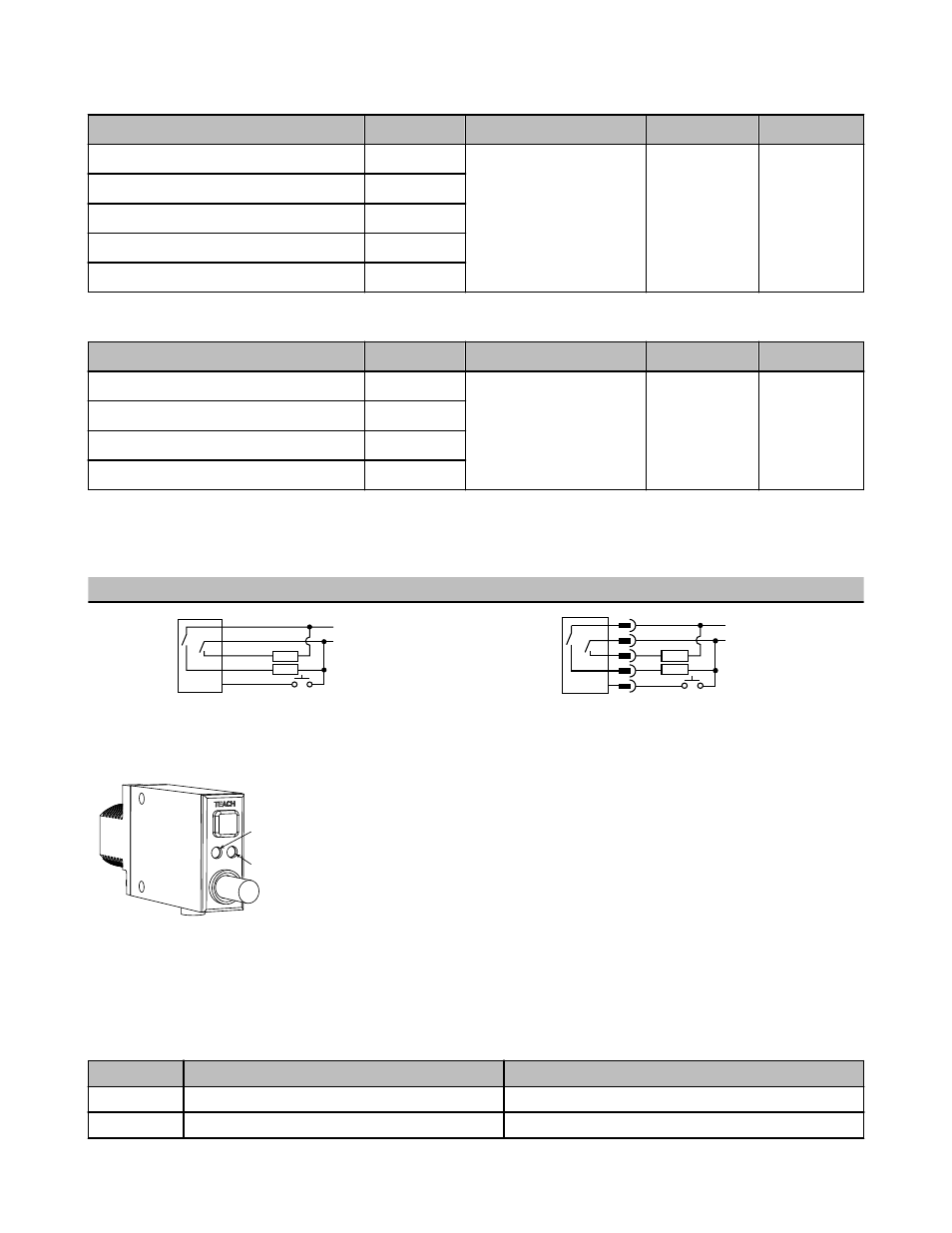
Wiring
Cabled Models
QD Models
bn
Remote
Teach
bu
wh
bk
gy
+
10-30V dc
–
Load
Load
bn
Remote
Teach
bu
wh
bk
gy
+
10-30V dc
–
Load
Load
Overview
Yellow output
indicator LED
Bi-color green/red
indicator LED
MINI-BEAM® Expert™ is a complete family of sensors, all housed in the popular, robust and compact rec-
tangular housing. Their large push button and easy-to-see indicators provide easy configuration, alignment,
and monitoring during use.
Status Indicators
Normal sensor operation is called RUN mode. Sensor configuration (setting the sensitivity threshold and selecting output ON and OFF conditions) is performed in TEACH
mode. The two LED indicators (bi-color green/red and yellow) have distinct roles in the two operation modes. If contrast is marginal, the bi-color indicator will flash green to
indicate instability. If this occurs, reconfigure or realign the sensor, or clean the sensor or fiber lenses.
The Signal Strength indicator is Banner’s exclusive AID™ (Alignment Indicating Device). Its pulse rate increases as the received light signal strength increases (during
programming). This feature simplifies accurate alignment during TEACH mode, and gives a relative indication of sensing contrast between the light and dark conditions.
LED
RUN Mode
TEACH Mode
Solid green
Power is on
Flashing green
Sensed light level is approaching sensing threshold*
MINI-BEAM Expert Series Installation Guide
2
www.bannerengineering.com - tel: 763-544-3164
P/N 068812 Rev. B