Q45xdn, Overview, Installation and removal – Banner Q45 Series User Manual
Page 2
Q45XDN
™
2
P/N 39667 rev. C
Banner Engineering Corp.
•
Minneapolis, MN U.S.A.
www.bannerengineering.com • Tel: 763.544.3164
The 45DN is one of a family of bus expansion cards for Q45X Series sensors which
includes models for use on AS-Interface, SDS
™
, and DeviceNet.
Use of a 45DN bus expansion card turns the Q45X into a “smart” sensor which can
be connected to a DeviceNet bus network using a simple “dumb drop” junction box or
a “T” connector. Plugging a bus expansion card into a Q45X Series sensor
automatically converts the basic sensor outputs to a pair of datacom connections with
the proper protocol for use on a DeviceNet bus network. Q45X sensors without bus
cards (i. e. “dumb sensors”) may also be added to any bus system, via a “smart
drop” junction box. Basic Q45X sensors (without bus expansion cards) interface
directly to PLC dc inputs. The block diagram below illustrates how “smart” and
“dumb” Q45X Series sensors can be mixed together on the same bus network.
Overview
Data
Input
Input
Input
PLC
Q45X
Q45X
Q45X
Q45X
Q45X
Q45X
Q45X
Q45X
Q45X
Q45X
Q45X
Q45X
“Dumb” Sensors
(x4)
“Smart” Sensors
(x4)
Smart
Drop
Dumb
Drop
“T”
“Dumb” Sensors
(x3)
“Smart” sensor
Connector
Bus
Installation and Removal
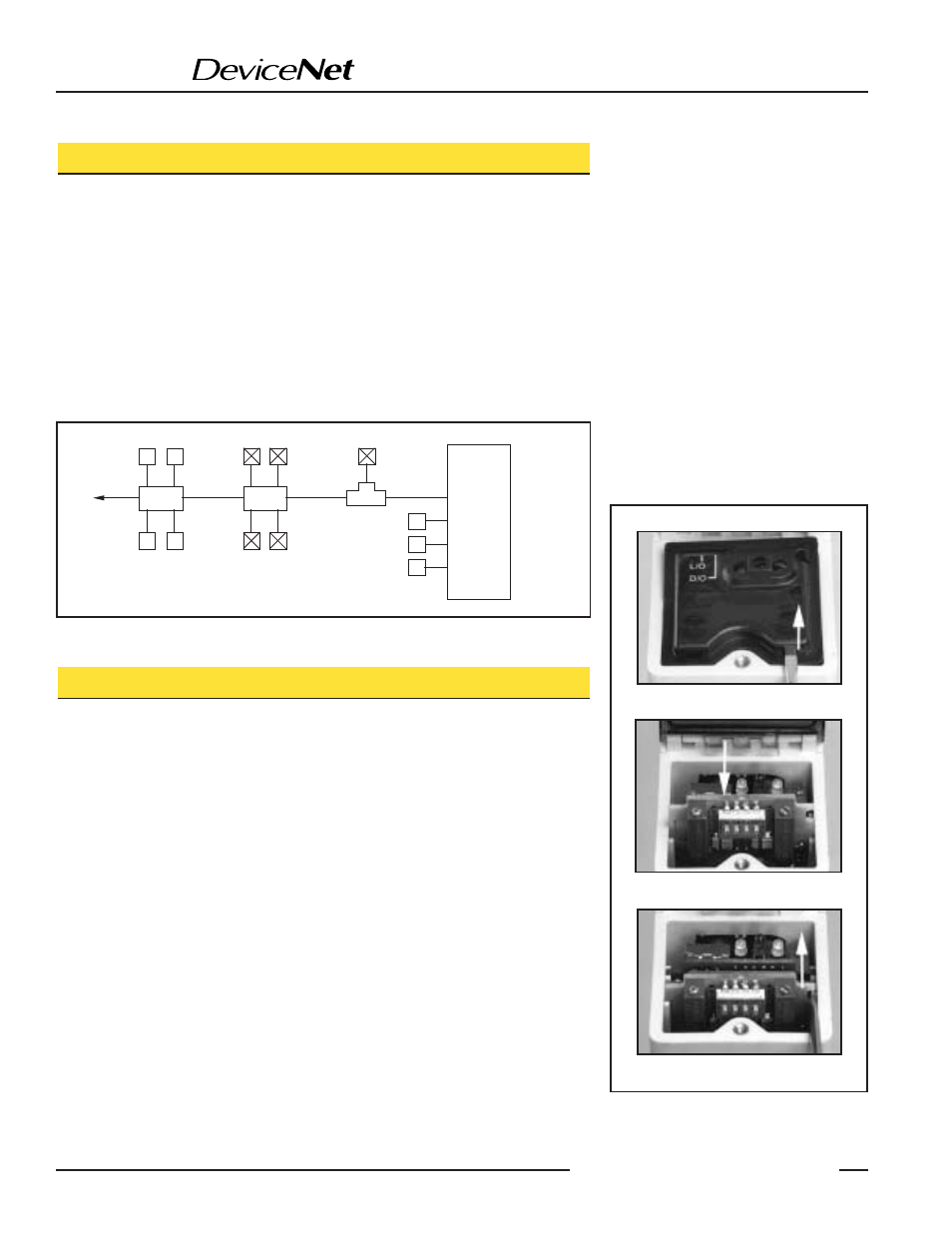
Modules are installed through the top of the sensor, as follows:
1) Remove power from the sensor.
2) Loosen the top cover hold-down screw and raise the cover. The cover is hinged at
the front.
3) Using a small screwdriver inserted into one of the slots at the rear of the inside
black cover, lift up and remove the black inside cover (Figure 2A).
4) Insert the card in the expansion slot so that the connector receptacles on the card
align with the connector pins inside the sensor. Slide the card down into the slot
until the connectors are fully engaged (Figure 2B).
5) Replace the original black inside cover with the one supplied with the 45DN card.
6) Make sure that the Light/Dark Operate switch in the Q45X sensor is set to the
Light Operate position.
Modules are removed through the top of the sensor, as follows:
1) Follow steps 1 through 3 of the installation procedure, above.
2) Insert a small, flat bladed screwdriver or similar tool into the lift slot on the edge
of the expansion card (Figure 2C). Gently pry up to disconnect the card, and then
lift it out.
3) Replace the black inside cover.
Figure 1. The same model Q45X “smart” and “dumb” sensors may be mixed on the same
bus system
A. Lift here
B. Slide board downward
C. Lift board up and out
Figure 2. Installation and removal of Bus
Expansion Cards