Sensor hookup diagrams, cl series maxi-amp modules, Use of auxiliary input (cl5 models) 3 warning – Banner MAXI-AMP Series User Manual
Page 3
PBT
1
2
3
4
MULTI-BEAM
CL3�
or �
CL5�
model
8
7
6
5
4
9
10
11
1
2
3
CL3�
or �
CL5�
model
8
7
6
5
4
9
10
11
1
2
3
MAXI-BEAM
4�
3�
2�
1
RPBT
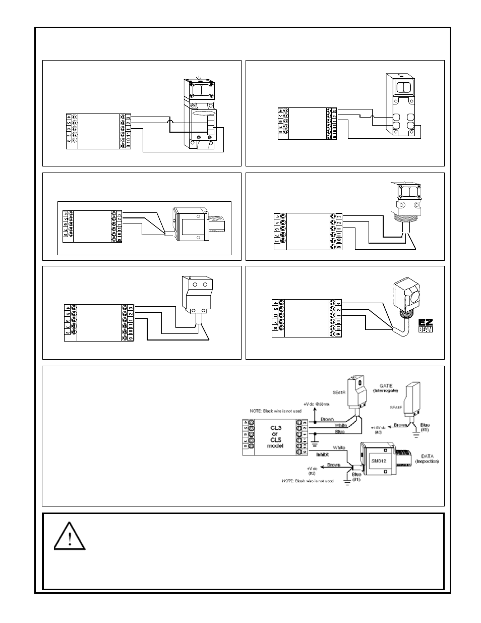
Sensor Hookup Diagrams, CL Series MAXI-AMP Modules
To MAXI-BEAM Sensors
To MULTI-BEAM Sensors
NOTE: the MAXI-AMP cannot power a MULTI-BEAM emitter and receiver pair.
Use a separate power source for the emitter (e.g.- power block PBA-1, etc.)
NOTE: use power block model RPBT.
NOTE: use power block model
PBT or PBT2.
To MINI-BEAM SM312 Series Sensors
To VALU-BEAM SM912 Series
Sensors
SM912
WHITE
BROWN
BLUE
NOTE: Black wire is not used
CL3�
or �
CL5�
model
8
7
6
5
4
9
10
11
1
2
3
To EZ-BEAM Sensors
NOTE: Black wire is not used
SE612
WHITE
BROWN
BLUE
CL3�
or �
CL5�
model
8
7
6
5
4
9
10
11
1
2
3
BROWN
BLUE
BLACK
CL3�
or �
CL5�
model
8
7
6
5
4
9
10
11
1
2
3
To ECONO-BEAM SE612
Series Sensors
NOTE: White wire is not used
This hookup is for DC NPN (current sinking) models of S18 Series, Q25 Series, and
other DC sensors bearing the EZ-BEAM logo.
CL5 model MAXI-AMPs have an auxiliary input at terminal #9 which may
be used for the interrogation or reset of the selected logic function. This is
accomplished by a switch closure between pins #9 and #1 (Common). The
auxiliary input may also be switched by a DC device with an NPN transistor
(current sinking) output. The effect of the auxiliary input is described for
each logic function on page 5.
This example shows a typical inspection/rejection scheme which uses a
Banner MINI-BEAM as the inspection sensor. Typically, the CL5 module
would be programmed for the ONE-SHOT or DELAYED ONE-SHOT logic
function. If the SM312 "sees" an acceptable condition when the SE612 senses
the leading (or trailing) edge of the product, the SM312 will inhibit a reject
pulse from occuring. Reject products will be ejected by the output pulse.
NOTE: the MAXI-AMP can supply 50mA for external 10 to 30V dc devices.
Carefully check the current draw of the devices to be powered by the MAXI-AMP.
Use of Auxiliary Input (CL5 models)
3
WARNING
The MAXI-AMP modules described in this data sheet do NOT include the self-checking redundant circuitry neces-
sary to allow their use in personnel safety applications. A failure or malfunction can result in
either an energized or a de-energized
output condition.
Never use these products for personnel protection. Their use as safety devices may create an unsafe condition which could lead to seri-
ous injury or death.
Only MACHINE-GUARD and PERIMETER-GUARD Systems, and other systems so designated, are designed to meet OSHA and ANSI machine safety
standards for point-of-operation guarding devices. No other Banner sensors or controls are designed to meet these standards, and they must NOT be used
as sensing devices for personnel protection.
NOTE: Black wire is not used
SM312
BROWN
BLUE
WHITE
CL3�
or �
CL5�
model
8
7
6
5
4
9
10
11
1
2
3
NOTE: black wire is not used.