Maxi-amp cl series specifications, Cl3 models, Dimension drawing cl5 models 2 generalized hookup – Banner MAXI-AMP Series User Manual
Page 2
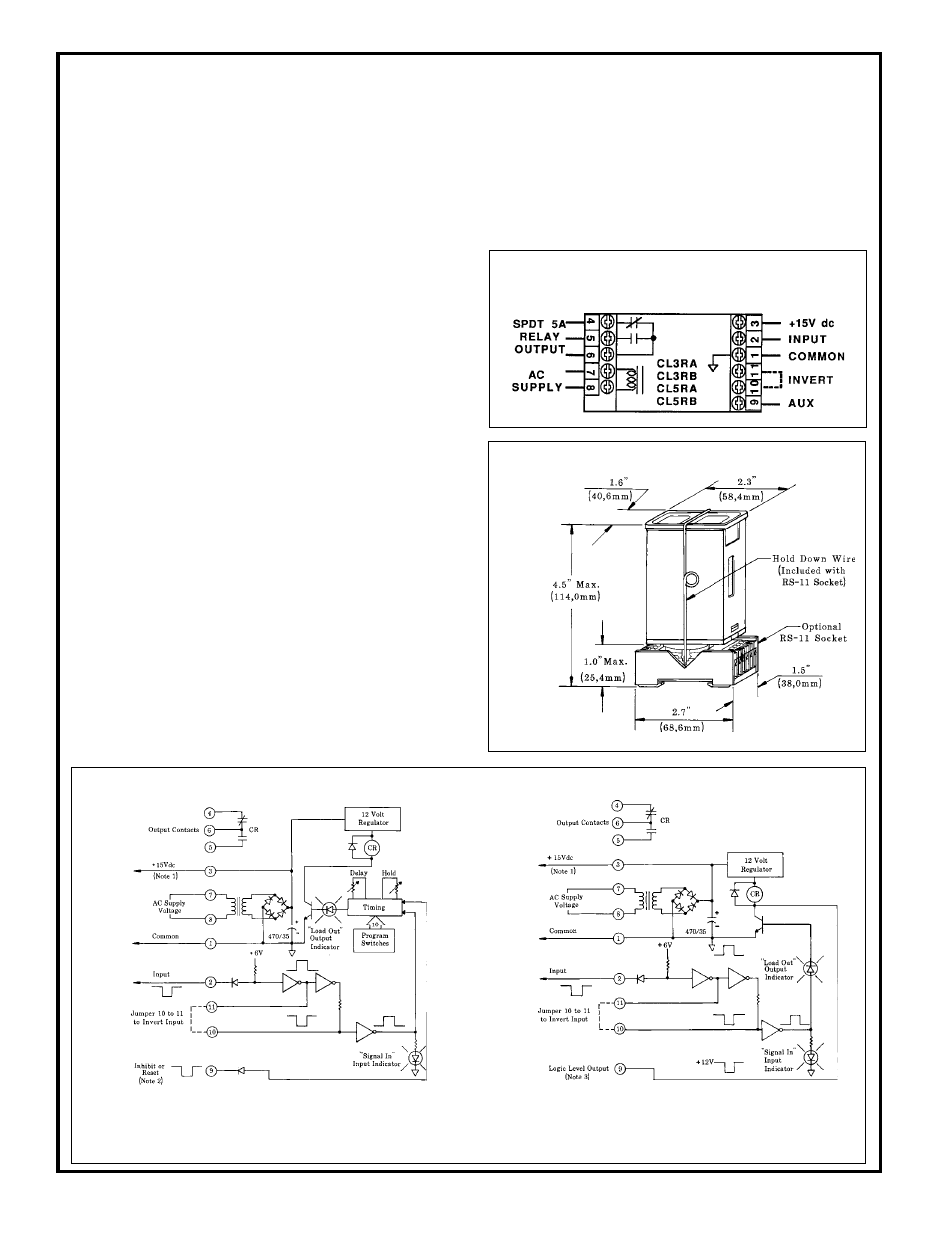
CL3 Models
NOTE #1: power is available at pins #3 (+) and #1 (-) for an external 10 to 30V dc device
(see hookup example). Current available is 50mA at 120V ac (240V ac) line level; 40mA
at 105V ac (210V ac) line level. Alternately, the module may be powered by 12 to 28V dc
at pins #3 (+) and #1 (-).
Do not connect ac voltage if using external dc power.
NOTE #2: pulling pin #9 low (to Common) will inhibit the timing, or reset the latch
of CL5 models. (See "Description of Logic Functions", page 5)
NOTE #3: pin #9 of model CL3RA and CL3RB may be connected directly to the pri-
mary or auxiliary input of MAXI-AMP model CL5 or to Banner Plug Logic modules.
Functional Schematics
Dimension Drawing
CL5 Models
2
Generalized Hookup:
models with electromechanical relay output
INDICATOR LEDs:
Red indicator LEDs for input and output
status.
CONSTRUCTION:
Rugged NORYL
®
polyphenylene oxide
(PPO
®
) housing, 1.6" x 2.3" x 4". Standard round-pin 11-pole plug
base.
OPERATING TEMPERATURE:
0 to 50 degrees C (32 to
122 degrees F).
SUPPLY VOLTAGE:
Models CL3RA, CL5RA: 105 to 130V ac,
50/60Hz (4 VA), or 12 to 28V dc* at 60mA. Models CL3RB, CL5RB:
210 to 250V ac, 50/60Hz (4 VA), or 12 to 28V dc at 60mA.
*Do not
connect ac voltage if using external dc power.
OUTPUT CONFIGURATION:
all models have SPDT electro-
mechanical relay:
CONTACT RATING: 250V ac max, 24V dc max, 5 amps max. (resis-
tive load), 1/10 H.P. at 240V ac. Install transient suppressor (MOV)
across contacts which switch inductive loads.
CLOSURE TIME: 10 milliseconds max.
RELEASE TIME: 10 milliseconds max.
MAXIMUM SWITCHING SPEED: 20 operations/second
MECHANICAL LIFE: 20,000,000 operations
CL3 models also have a logic level current sinking NPN transistor
switch at pin #9. See schematic below and hookup info.
AMPLIFIER:
RESPONSE SPEED: 1 millisecond
INPUT CHARACTERISTICS: input is switched when the voltage at
pin #2 is pulled below 1V dc or when less than 1K ohms is connected
between pins #2 and #1. When an inverting jumper is connected be-
tween pins #10 and #11, input is switched when the voltage at pin #2
rises above 4.5V dc or when the impedance between pins #2 and #1
exceeds 15K ohms.
HYSTERESIS: greater than .35 volts, less than 2 volts.
MULTIPLE SENSOR HOOKUP: any number of switched output
devices may be connected in parallel to the input (see hookup ex-
ample).
TIMERS (CL5 models only):
TIME RANGES: LOW range - 10 to 150 milliseconds
MIDDLE range - 0.1 to 1.5 seconds
HIGH range - 1 to 15 seconds
REPEATABILITY: +/-2% of set time over all extremes of
supply voltage and temperature
ADJUSTMENTS:
Miniature switches for setting of timing func-
tion, timing range, and output polarity (CL5 models). 15-turn clutched
potentiometer for time setting (CL5 models).
MAXI-AMP CL Series Specifications