Valu-beam, 915 series, 915 series retroreflective mode – Banner VALU-BEAM Series User Manual
Page 2: Non-polarized, Polarized, Effective beam: 3.5 mm
VALU-BEAM –
915 Series
page
2
Banner Engineering Corp. • Minneapolis, U.S.A.
Website: http://www.baneng.com • Tel: 888.373.6767
Infrared, 880 nm
915 Series Opposed-Mode Emitter (E) and Receiver (R)
SMA91ESR
SMA95RSR
SMA91ESRQD
SMA95RSRQD
Emitter:
10 to 250V
ac/dc
Receiver:
90 to 130V ac
2 m (6.5')
2 m (6.5')
3-Pin Mini QD
5-Pin Mini QD
Models
Range
Cable*
Supply
Voltage
Output
Type
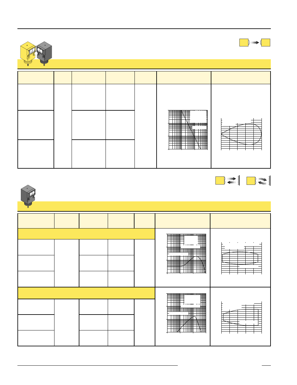
Excess Gain
Beam Pattern
SMA91ESR
SMW95RSR
SMA91ESRQD
SMW95RSRQD
3 m
(10')
2 m (6.5')
2 m (6.5')
3-Pin Mini QD
5-Pin Mini QD
Emitter:
10 to 250V
ac/dc
Receiver:
12 to 28V dc
SPDT
E/m
Relay
1
10
100
.10 m
.33 ft
1.0 m
3.3 ft
10 m
33 ft
.01 m
.033 ft
E
X
C
E
S
S
G
A
I
N
DISTANCE
1000
SMA91ESR &
SMW95RSR or
SMA95RSR or
SMB95RSR
Opposed Mode
3.0 m
10ft
2.4 m
8 ft
1.8 m
6 ft
1.2 m
4 ft
.6 m
2 ft
0
0
100 mm
200 mm
300 mm
100 mm
200 mm
300 mm
0
4.0 in
8.0 in
12.0 in
4.0 in
8.0 in
12.0 in
DISTANCE
SMA91ESR with SMW95RSR
or SMA95RSR / SMB95RSR
Opposed Mode
SMA91ESR
SMB95RSR
SMA91ESRQD
SMB95RSRQD
2 m (6.5')
2 m (6.5')
3-Pin Mini QD
5-Pin Mini QD
Emitter:
10 to 250V
ac/dc
Receiver:
210 to 250V ac
P
Visible red, 650 nm
Non-Polarized
Polarized
Non-Polarized,
Polarized
**Retroreflective range is specified using one model BRT-3 retroreflector (3" diameter). Actual sensing range may be more or less than specified,
depending upon the efficiency and reflective area of the retroreflector(s) in use. See your Banner Photoelectric catalog for more information.
915 Series Retroreflective Mode
SMA915LV
SMA915LVQD
SMB915LV
SMB915LVQD
SMA915LVAG
SMA915LVAGQD
90 to 130V ac
SMB915LVAG
SMB915LVAGQD
2 m (6.5')
5-Pin Mini QD
Models
Range**
Cable*
Supply
Voltage
Output
Type
Excess Gain
Beam Pattern
Non-Polarized
90 to 130V ac
2 m (6.5')
5-Pin Mini QD
2 m (6.5')
5-Pin Mini QD
Polarized
1
10
100
.10 m
.33 ft
1.0 m
3.3 ft
10 m
33 ft
.01 m
.033 ft
E
X
C
E
S
S
G
A
I
N
DISTANCE
1000
SMW915LV,
SMA915LV,
SMB915LV
Retroreflective Mode
with BRT-3 reflector
10 m
33 ft
8 m
26 ft
6 m
20 ft
4 m
13 ft
2 m
6.5 ft
0
0
50 mm
100 mm
150 mm
50 mm
100 mm
150 mm
0
2.0 in
4.0 in
6.0 in
2.0 in
4.0 in
6.0 in
DISTANCE
SMW915LV, SMA915LV, SMB915LV
Retroreflective Mode
With BRT-3 Reflector
210 to 250V ac
2 m (6.5')
5-Pin Mini QD
1
10
100
.10 m
.33 ft
1.0 m
3.3 ft
10 m
33 ft
.01 m
.033 ft
E
X
C
E
S
S
G
A
I
N
DISTANCE
1000
SMW915LVAG,
SMA915LVAG,
SMB915LVAG
Retroreflective Mode
with BRT-3 reflector
5 m
16 ft
4 m
13 ft
3 m
10 ft
2 m
6.6 ft
1 m
3.3 ft
0
0
25 mm
50 mm
75 mm
25 mm
50 mm
75 mm
0
1.0 in
2.0 in
3.0 in
1.0 in
2.0 in
3.0 in
DISTANCE
SMW915LVAG, SMA915LVAG,
SMB915LVAG
Retroreflective Mode
With BRT-3 Reflector
210 to 250V ac
SMW915LV
SMW915LVQD
SMW915LVAG
SMW915LVAGQD
0.3 to 4.5 m
(1' to 15')
2 m (6.5')
5-Pin Mini QD
0.15 to 9 m
(6" to 30')
12 to 28V
ac/dc
SPDT
E/m
Relay
2 m (6.5')
5-Pin Mini QD
12 to 28V
ac/dc
SPDT
E/m
Relay
Opposed-mode sensors have higher excess gain than other models, and so should be
used whenever possible. ESR and RSR models’ small effective beam size enables them to
reliably detect relatively small objects; their wide beam angle allows forgiving alignment
within the 10’ range.
An excellent alternative when opposed-mode sensing is not possible. A visible red
beam reduces the potential for false signals from reflective objects (“proxing”)
and simplifies alignment. AG (anti-glare) models polarize the emitted light and
filter out unwanted reflections.
Effective Beam: 3.5 mm