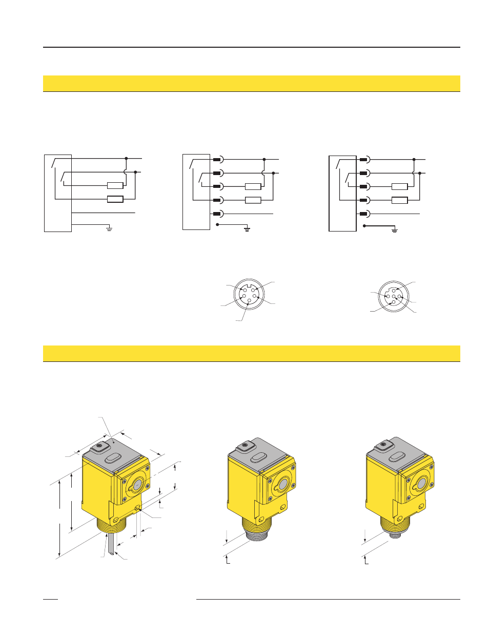
U-gage, Q45u series hookup diagrams q45u series dimensions, Pin mini-style pin-out (cable connector shown) – Banner U-GAGE Q45U Series—Analog User Manual
Page 7: Pin euro-style pin-out (cable connector shown)
U-GAGE
™
Q45U Ultrasonic Sensors with Bipolar Discrete Outputs
P/N 44177 Rev. D
7
Banner Engineering Corp.
•
Minneapolis, MN U.S.A.
www.bannerengineering.com • Tel: 763.544.3164
Q45U Sensor with 5-Pin
Mini-Style QD
(“Q” model Suffix)
Q45U Sensor with Attached Cable
bn
wh
bu
+
–
bk
ye or gy
Load
12-24V dc
Enable
(+5-24V dc)
Load
shield*
bn
wh
bu
+
–
bk
ye
Load
Load
12-24V dc
Enable
(+5-24V dc)
shield*
Q45U Sensor with 5-Pin
Euro-Style QD
(“Q6” model Suffix)
bn
wh
bu
+
–
bk
gy
Load
Load
12-24V dc
Enable
(+5-24V dc)
shield*
5-Pin Mini-Style Pin-out
(Cable Connector Shown)
Black Wire
Blue Wire
Brown Wire
Yellow Wire
White Wire
5-Pin Euro-Style Pin-out
(Cable Connector Shown)
White Wire
Blue Wire
Black Wire
Brown Wire
Gray Wire
14 mm (0.6")
Q45U Sensor with Attached Cable
Q45U Sensor with 5-Pin Mini-Style QD
(“Q” model Suffix)
15 mm (0.6")
Q45U Sensor with 5-Pin Euro-Style QD
(“Q6” model Suffix)
Q45U Series Hookup Diagrams
Q45U Series Dimensions
60.5 mm
(2.38")
44.5 mm
(1.75")
69.0 mm
(2.72")
87.6 mm
(3.45")
30.0 mm
(1.18")
7.1 mm
(0.28")
4.5 mm (#10) Screw
Clearance (2)
50.8 mm
(2.00")
6.4 mm (0.25")
Transducer
Centerline
Internal Thread
(1/2–14NPSM)
External Thread
M30 X 1.5
ø 6.1 (0.24")
2m (6.5') Cable
Hex Nut Supplied
Transparent Cover (Gasketed)
View: Sensing Status
Output Load Status
Power
Open to Access:
Push Button for
Programming of Sensing
Window Limits
*It is recommended that the shield wire be connected
to earth ground or dc common.