U-gage – Banner U-GAGE Q45U Series—Analog User Manual
Page 4
U-GAGE
™
Q45U Ultrasonic Sensors with Bipolar Discrete Outputs
4
P/N 44177 Rev. D
Banner Engineering Corp.
•
Minneapolis, MN U.S.A.
www.bannerengineering.com • Tel: 763.544.3164
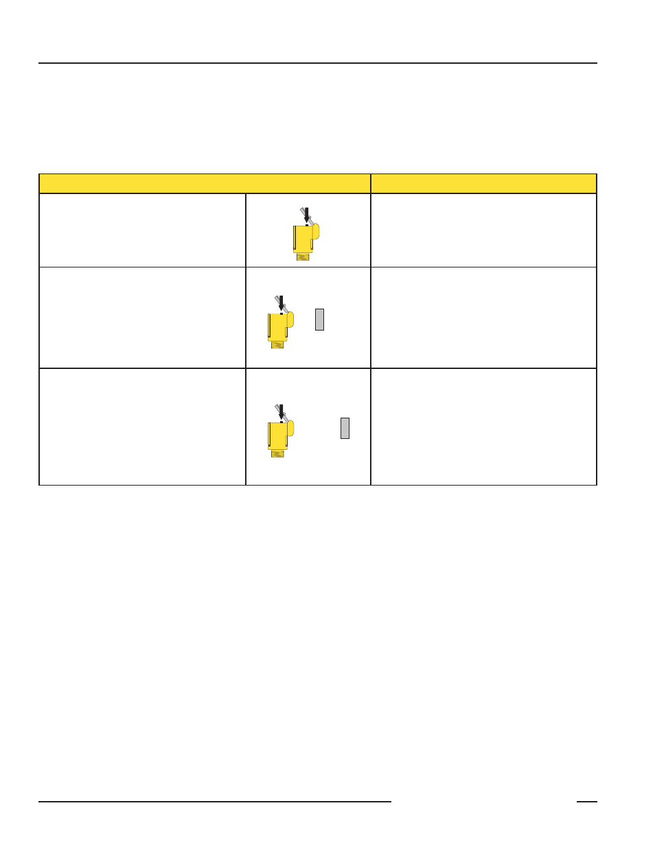
Push Button
Indicator Status
Step 1
Push and hold until green indicator turns off
(approximately 2 seconds)
Push and Hold for
≥ 2 Seconds
Green: Goes off
Yellow: Is on steadily to indicate ready for teaching
first limit
Red:
Flashes to indicate strength of echo or is
off if no target is present
Step 2
FIRST LIMIT (Near or Far)
Place the target at the first limit and press the
push button for less than 2 seconds
Push for < 2 Seconds
Target at
First Limit
Green: Remains off
Yellow: Flashes at 2 Hz to indicate ready for
teaching second limit
Red:
Comes on steadily for a moment, then
resumes flashing to indicate strength of
echo
Step 3
SET SECOND LIMIT (Far or Near)
Place the target at the second limit and press
the push button for less than 2 seconds
Push for < 2 Seconds
Target at
Second Limit
Green: Remains off, then comes on steadily
(returns to RUN mode)
Yellow: On steadily for a moment, then is either on
or off to indicate output state (returns to
RUN mode)
Red:
Comes on steadily for a moment, then
resumes flashing to indicate strength of
echo (returns to RUN mode)
Notes regarding window limit programming:
1) Either the near or far limit may be programmed, first.
2) There is a 2-minute timeout for programming of the first limit. The sensor will return to RUN mode with the previously
programmed limits. There is no timeout between programming of the first and second limit.
3) The programming sequence may be cancelled at any time by pressing and holding the push button for
≥ 2 seconds. The sensor
returns to RUN mode with the previously programmed limits.
4) During limit programming, the 5-segment moving dot indicator displays the relative target position between 0 and 1500
millimeters (the maximum recommended far limit position is 1400 mm).
5)
If the target is positioned between 1400 and 1500 mm, the 5th segment of the moving dot indicator flashes to indicate that a
valid echo is received, but the target is beyond the recommended 1400 mm maximum far limit.
6)
If a limit is rejected during either programming step, the sensor will revert to the first limit programming step (Step 2 in
programming chart). This will be indicated by Green - off, Red - flashing to indicate signal strength, and Yellow - on steadily.
7)
If both limits are accepted, the sensor will return to RUN mode, which is indicated by the Green LED coming on steadily.
8) If the target is held at the same position for programming of both limits, the sensor will establish a 10-mm wide sensing
window, centered on the target position.
Window Limit Programming
The “Limits” push button, located under the transparent top cover, is used to program the near and the far limits. The near limit may
be set as close as 100 millimeters (4") and the far limit may be set as far as 1400 mm (55") from the transducer face. Minimum
window width is 10 mm (0.4"). Whenever possible, use the actual target to be sensed when setting the window limits. The following
procedure begins with the sensor in RUN mode.