Banner PS115-1 Sensor Interface Power Supplies User Manual
Page 2
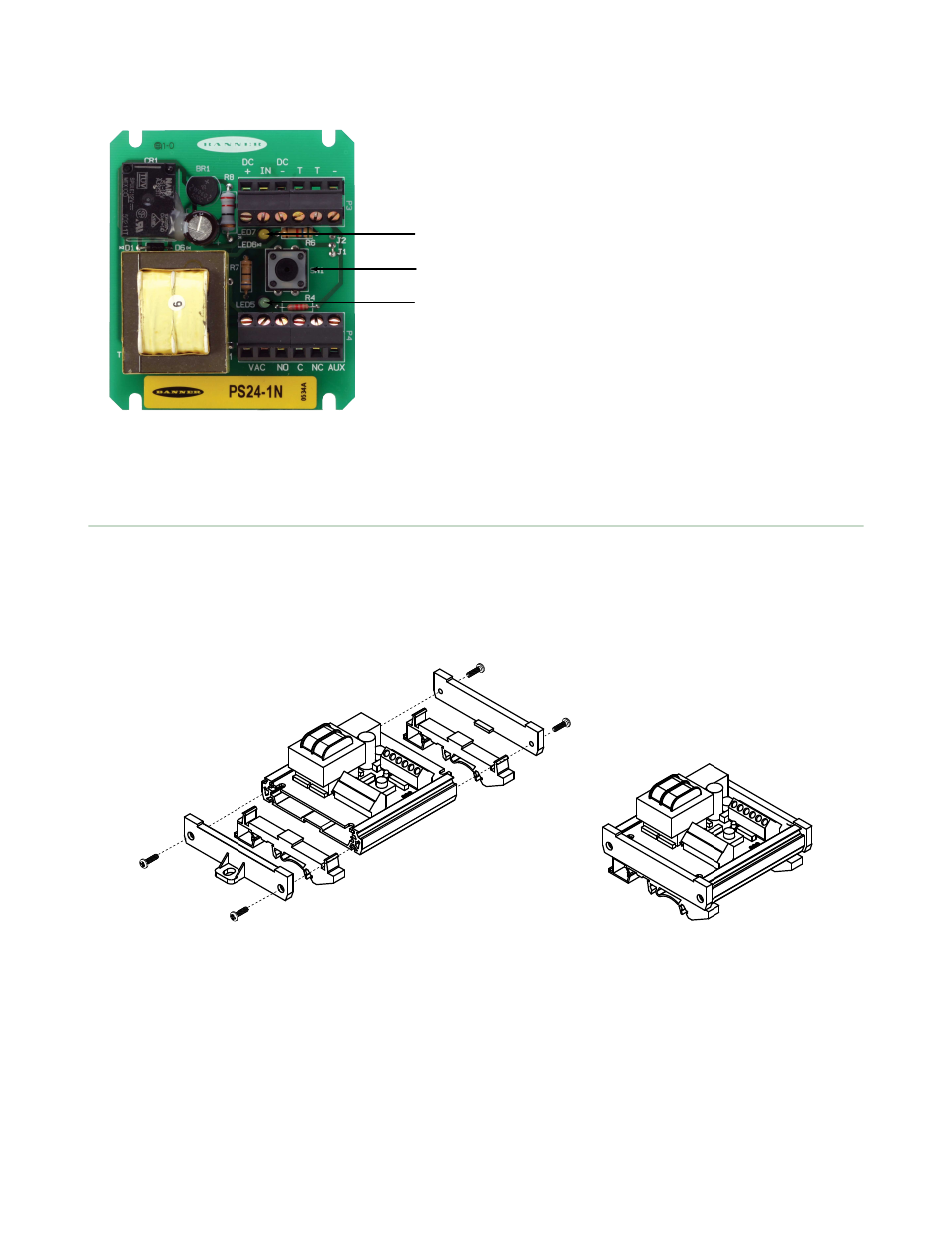
1
2
3
1. Output Indicator LED (amber)
2. TEACH button
3. Power Indicator LED (green)
Installing the PS24-1 or PS115-1 Power Supply
The module must be isolated from conductive surfaces. It may be installed in a user-supplied housing using the four slots
in the board’s corners, or it may be inserted into the supplied plastic housing.
When you use the supplied housing, either insert the two DIN clips into the grooves on the housing’s underside and add
the two end caps (shown), or install only the end caps and use the screw-holes in the end caps for mounting to a flat
surface. Screws are provided for attaching the end caps to the housing.
PS24-1 and PS115-1 Sensor Interface Power Supplies
2
www.bannerengineering.com - tel: 763-544-3164
P/N 123566 Rev. C
This manual is related to the following products: