Banner PS115-1 Sensor Interface Power Supplies User Manual
Datasheet, Overview
Datasheet
Optional mounts, plastic housing and
brackets included.
•
Low-cost interface between ac power supply and dc-operated
sensors
•
Power supply can source up to 100 milliamps
•
Integral TEACH push button and remote TEACH function available
on all models
•
Integral SPDT relay isolates dc sensor output for ac applications
•
LED indicators for Power ON and Output Active
•
Easy-to-adjust 45° screw terminals for all electrical wiring
•
Multiple mounting configurations using supplied hardware
•
BENC-L enclosure available for NEMA 4X / IP55 applications
•
Use a sinking (NPN) interface module model with an NPN-output
sensor, and a sourcing (PNP) interface module model with a PNP-
output sensor.
Models
Input
Output
Relay Input
PS24-1N
21 to 27V ac, 50/60 Hz
100 mA
Sinking (NPN)
PS24-1P
Sourcing (PNP)
PS115-1N
105 to 130V ac, 50/60 Hz
Sinking (NPN)
PS115-1P
Sourcing (PNP)
A sinking (NPN) interface module model must be used with an NPN-output sensor, and a sourcing (PNP) interface module
model must be used with a PNP-output sensor.
Overview
This interface module combines the functions of a power supply, a TEACH button, and an SPDT relay to economically
interface dc-operated sensors for ac applications. The interface accepts either a 24V ac or 115V ac power supply,
depending on the model. It uses a transformer to isolate the input power supply from the dc sensor. The transformer
output voltage is rectified and filtered to supply up to 100 milliamps to run dc sensors.
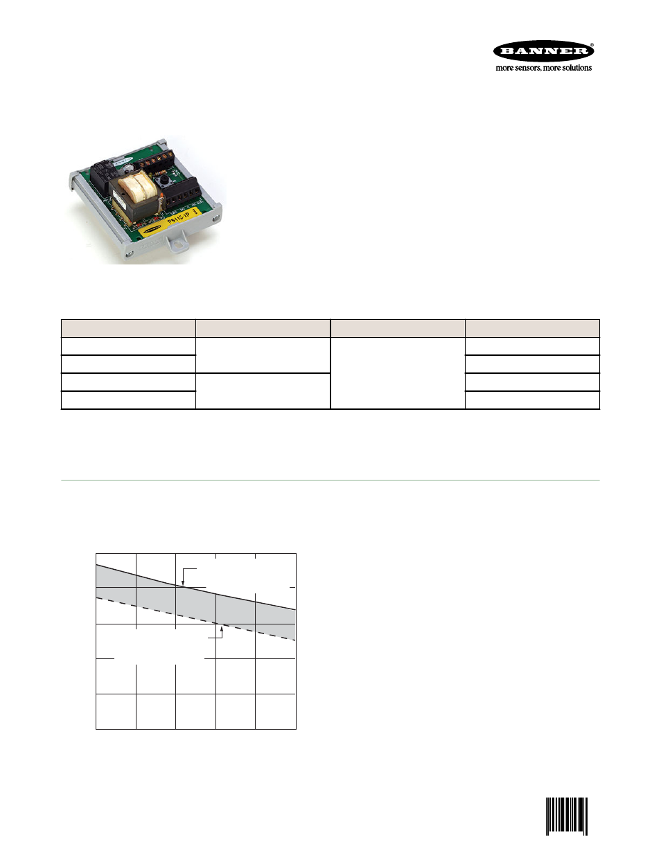
25
20
20
40
60
80
100
15
10
5
0
0
Load Current dc (milliamps)
V Output (dc)
NOTE: Ripple voltage is less than 1.2V at 100 mA load
Minimum AC Input Voltage
21V ac (PS24-1..)
105V ac (PS115-1..)
Maximum AC Input Voltage
27V ac (PS24-1..)
130V ac (PS115-1..)
An integral TEACH button can be used to activate the
TEACH functions of a Banner Expert
™
sensor. Remote
TEACH capability also is available on all models (refer to
hookup diagrams and sensor literature).
The SPDT relay is controlled via the relay coil input. A dc
sensor output (either sinking or sourcing, depending on
interface module model) can be tied to the relay coil input.
The module's amber LED is ON when the sensor output is
active. The module's green LED is used as a power
indicator.
For sensor supply voltage and current requirements, refer
to the chart.
PS24-1 and PS115-1 Sensor Interface
Power Supplies
P/N 123566 Rev. C
9 Oct 2013
0 123566
1