Omni-beam sensor heads, Measuring sensing contrast, Contrast values and corresponding guidelines – Banner OMNI-BEAM Series User Manual
Page 7
OMNI-BEAM Sensor Heads
page
7
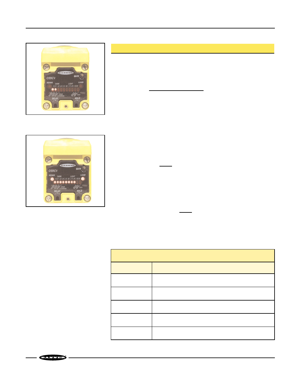
Figure 8. Dark condition example:
D.A.T.A. system LEDs #1
and #2 lit.
Figure 9. Light condition example:
D.A.T.A. system LEDs
#1 through #8 lit.
Measuring Sensing Contrast
Contrast is the ratio of the amount of light falling on the receiver in the “light” state,
compared to the “dark” state (sometimes called “light-to-dark ratio”). Optimizing the
contrast in any sensing situation increases the sensing reliability. Contrast may be
calculated if excess gain values are known for both the light and dark conditions:
Contrast = Excess gain (light condition)
Excess gain (dark condition)
To determine the contrast for any sensing application, present both the Light and Dark
conditions to the OMNI-BEAM, and note how many LEDs in the D.A.T.A. display are
ON for each condition. Compute the ratio from the corresponding excess gain
numbers (from the chart on page 6) for the two conditions.
For example, if LEDs #1 through #8 come ON in the Light condition and LEDs #1 and
#2 come ON in the Dark condition (assuming Standard scale factor), contrast is
calculated as follows:
Light condition: 2.2x excess gain
Dark condition: 0.35x excess gain
Contrast = 2.2x
= 6
0.35x
This value is expressed as 6:1 (“six-to-one”).
The best sensor adjustment will cause all ten D.A.T.A. LEDs to come ON for the Light
condition, and none in the Dark condition. In this situation (such as an application in
which a box breaks the beam of an opposed-mode emitter/receiver pair):
Contrast is greater than
3.7x = 15
0.25x
While it is not always possible to adjust a sensor to maintain this much contrast, it is
important to always adjust for the maximum possible contrast. The D.A.T.A. feature
makes this easy. The chart below gives general guidelines for contrast values.
Contrast Values and Corresponding Guidelines
Contrast
Recommendation
1.2 or Less
Unreliable. Evaluate alternative sensing schemes.
1.2 to 2
Poor Contrast. Use the LOW hysteresis setting and the FINE
scale factor.
2 to 3
Low Contrast. Sensing environment must remain perfectly clean and
all other sensing variables must remain stable.
3 to 10
Good Contrast. Minor sensing system variables will not affect
sensing reliabilty.
10 or Greater
Excellent Contrast. Sensing should remain reliable as long as the
sensing system has enough excess gain for operation.