Mini-beam, Sensors, Mounting brackets – Banner MINI-BEAM Series User Manual
Page 6: Model description dimensions
MINI-BEAM
®
Sensors
SM312LV, SM312LVAG and SM312LP
page
6
Banner Engineering Corp.
•
Minneapolis, U.S.A.
www.bannerengineering.com • Tel: 763.544.3164
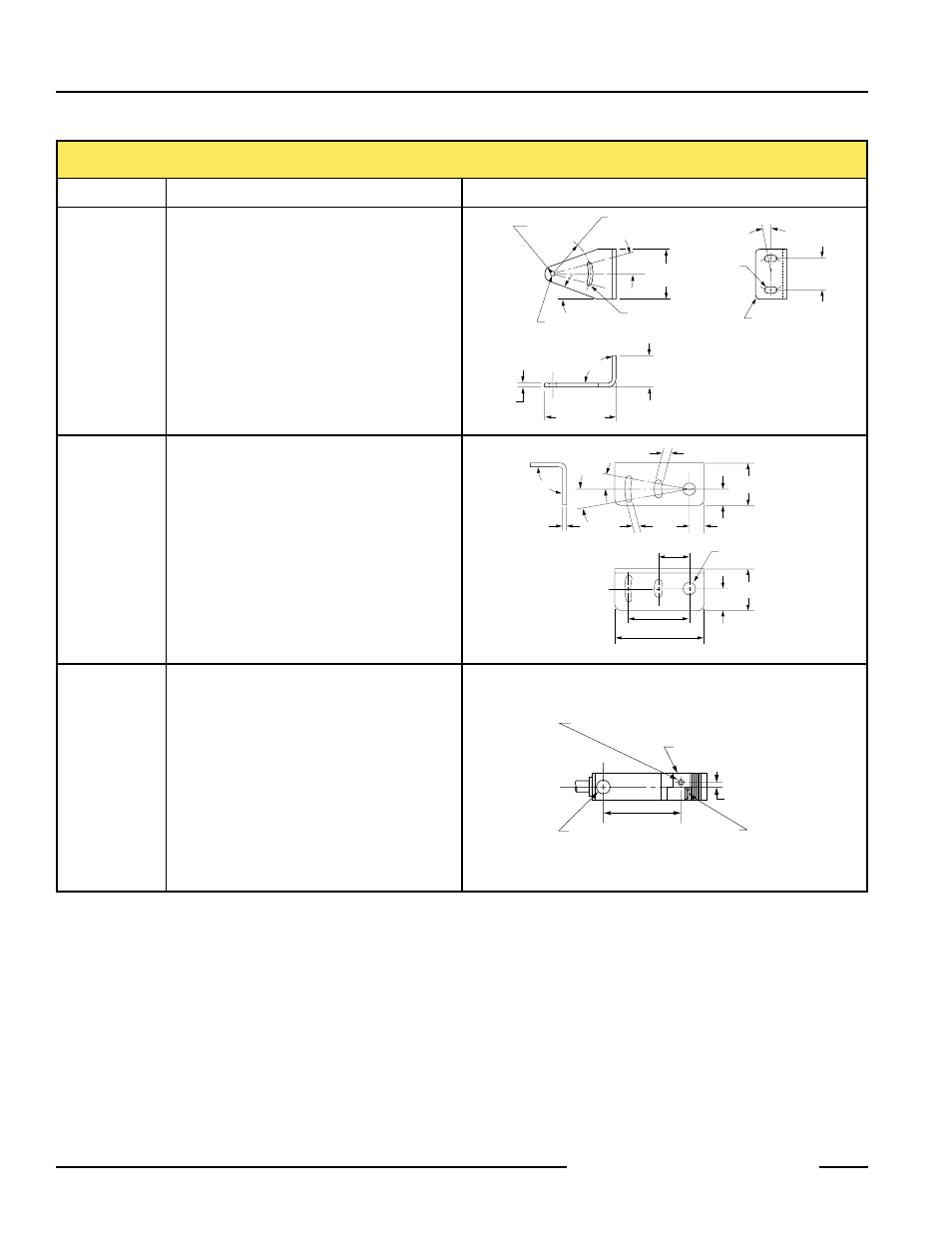
Mounting Brackets
Model
Description
Dimensions
R 5.1 mm
(0.20 in)
ø 3.05 mm
(0.120 in)
ø 3.05 mm Slot
(0.120 in)
20
°
90
°
CL
15
°
(2)
R 24.1 mm
(0.95 in)
31.8 mm
(1.25 in)
20.1 mm
(0.79 in)
45.5 mm
(1.79 in)
20.3 mm
(0.80 in)
R 3.1 mm
(0.12 in) (2)
10
°
(TYP)
4.32 mm
(0.170 in)
Slot (2)
2.5 mm
(0.10 in)
SMB312S
Stainless steel 2-axis, side mounting bracket
90
°
10
°
(2)
10
°
(2)
2.5 mm
(0.10 in)
3.1 mm
Slot (2)
(0.12 in)
4.3 mm Slot (2)
(0.17 in)
8.6 mm (2)
(0.34 in)
ø 6.9 mm
(0.27 in)
17.3 mm (2)
(0.68 in)
35.0 mm (2)
(1.38 in)
50.8 mm
(2.00 in)
23.4 mm
(0.92 in)
11.4 mm
(0.45 in)
9.1 mm
(0.36 in)
24.1 mm
(0.95 in)
SMB312B
Stainless steel 2-axis, bottom mounting bracket
Includes SMB12F (below)
#4-40 x 5 mm ( 0.2 in) Deep Thread
#4-40 x 6.4 mm (0.25 in) Screw is Supplied
SMB312F
Mounting Foot
2.3 mm
(0.09 in)
35.0 mm
(1.38 in)
Mounting Peg
ø 6.4 mm (0.25 in) x
2.5 mm (0.10 in) High
Screw to Hold
Mounting Foot to
Sensor Body (Supplied)
CL
SMB312F
• A mounting foot used to attach to bottom
surface of any MINI-BEAM sensor to a flat
mounting surface
• Attaches securely beneath the MINI-BEAM
sensor’s barrel using a special extra-long upper
cover mounting screw (supplied)