Bird Technologies 81-37-25 Series User Manual
Page 9
TX RX Systems Inc. Manual 7-9095-3 01/17/06 Page 5
7) Set the A-7550 for 2 dB per division vertical
scale and set a zero dB insertion loss reference
as outlined in paragraph 1.
8) Connect the A-7550 to the isolator as shown in
Figure 6, Adjust capacitors 3 and 4 for a cen-
tered and symmetrical response.
9) Set the A-7550 for 10 dB per division and reset
the zero dB insertion loss reference per para-
graph 1.
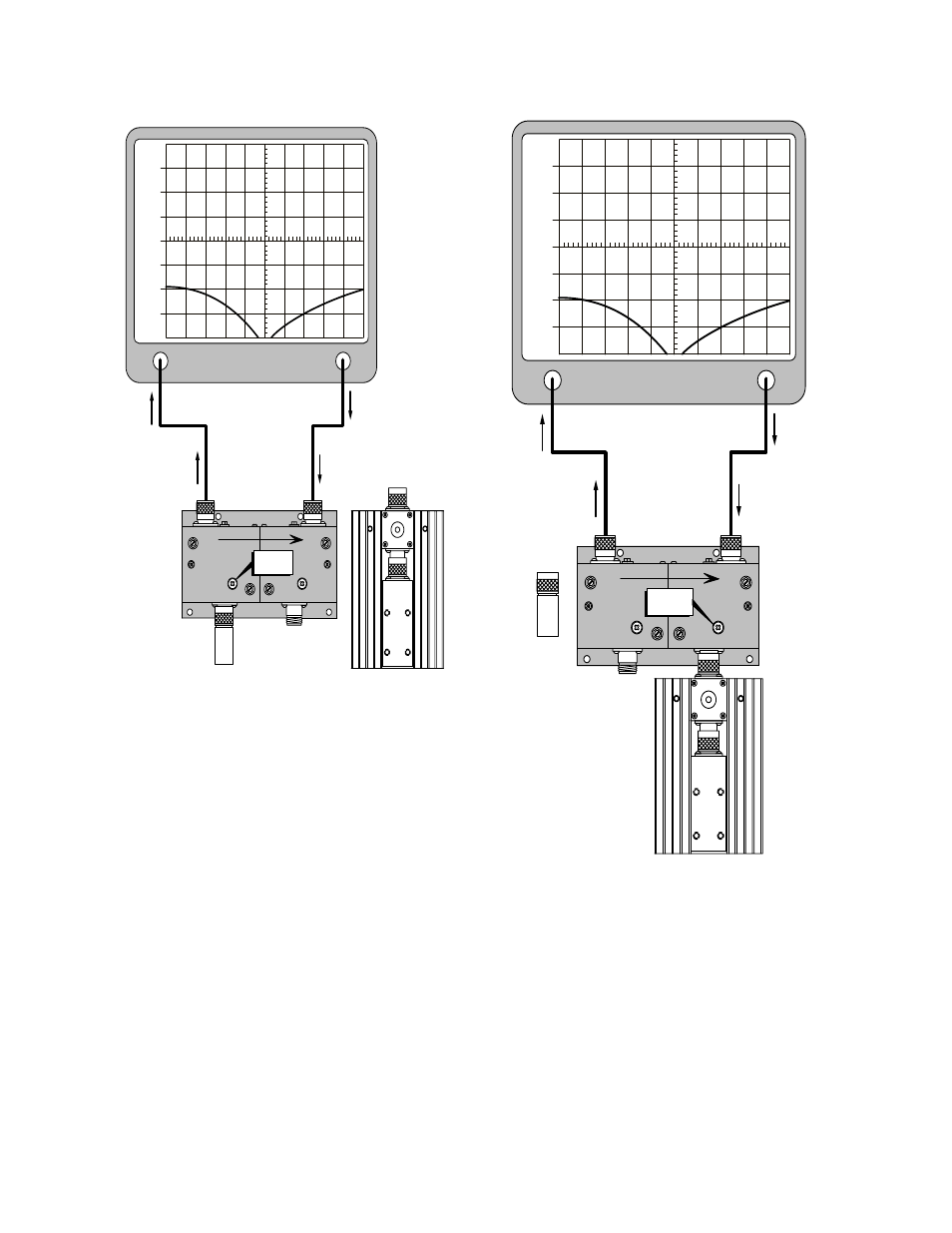
10) Connect the equipment as shown in Figure 7
and adjust capacitor 5 for maximum attenua-
tion (reverse isolation). Be sure to remove the
output load as this allows the observation of
the isolation produced by a single section.
11) Reconnect the output load and disconnect the
input load as shown in Figure 8. Adjust capac-
itor 6 for maximum attenuation (reverse isola-
tion). Then reconnect the input load.
12) Repeat steps 4 through 12. The isolator is now
ready to be put back in service.
Analyzer
Input
Generate
Output
TUNE
RF
Load
Removed
+30
+20
+10
0
-10
-20
-30
1
5
3
4
6
2
Figure 7: Tuning for reverse isolation.
Analyzer
Input
Generate
Output
TUNE
RF
Load
Removed
+30
+20
+10
0
-10
-20
-30
1
5
3
4
6
2
Figure 8: Tuning for reverse isolation.