Bird Technologies 81-37-25 Series User Manual
Page 5
TX RX Systems Inc. Manual 7-9095-3 01/17/06 Page 1
GENERAL DESCRIPTION
Isolators perform two important functions. Their pri-
mary function is to keep other RF frequencies out
of the transmitter so that intermodulation products
cannot be generated. isolators have a substantial
amount of reverse isolation. They also insure that
the transmitter never sees any significant reflected
power so it will always operate with maximum sta-
bility at full-power output. Isolators prevent energy
from getting to the transmitters output by dumping
RF energy entering the output of the isolator into a
dummy load.
This manual deals primarily with the procedures
necessary for field tuning ferrite isolators to new
frequencies. It is assumed that procedures in this
manual will be carried out by a skilled electronics
technician who is familiar with the communications
system. For a more detailed discussion of the con-
struction and theories of operation of ferrite isola-
tors refer to the TX RX Systems Inc. publication
“SEMINAR SUBJECTS” titled “An Elementary
Introduction to Ferrite Isolators, Circulators and RF
Loads” (literature number C2003H92). Contact
your TX RX Systems sales representative if you
wish to order a copy.
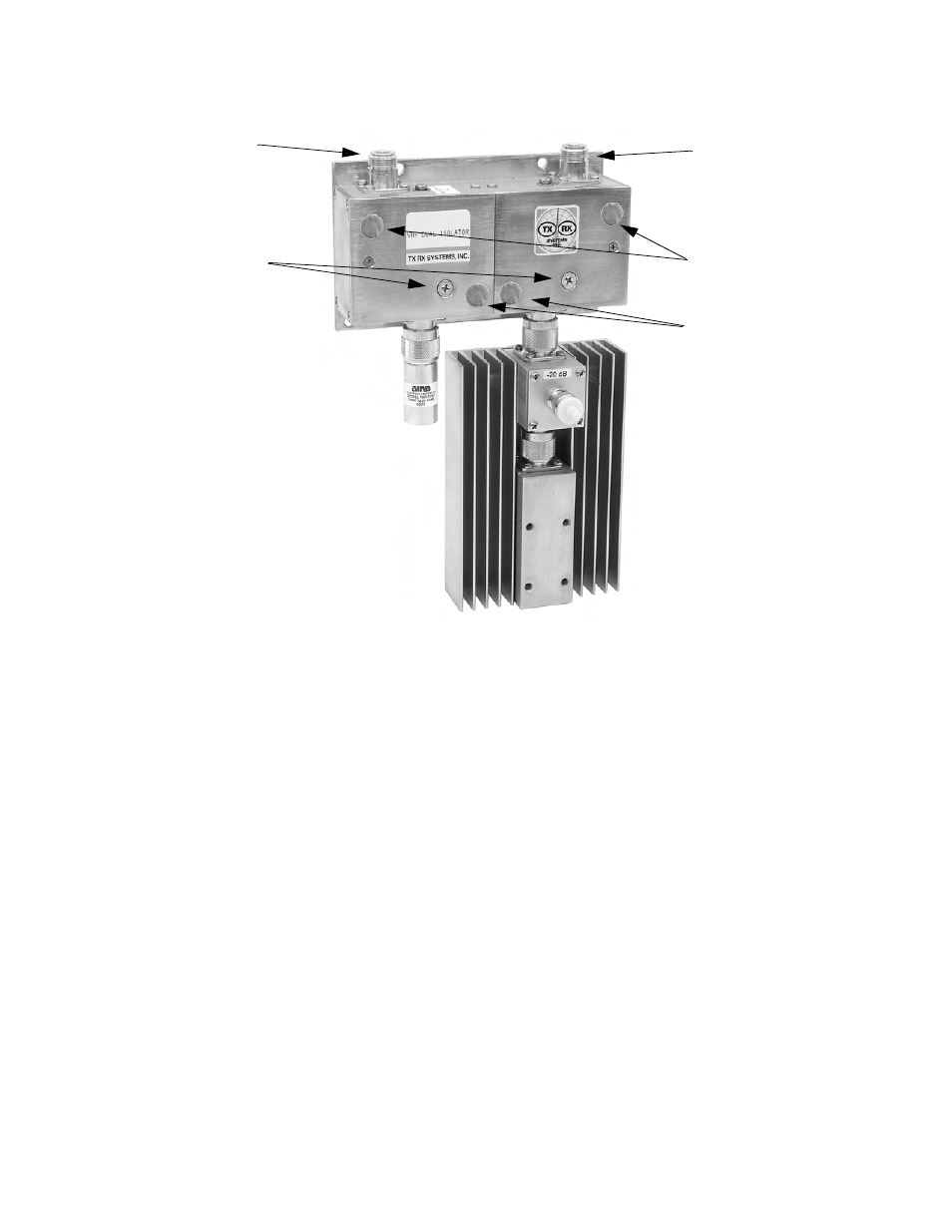
Dual-Section Isolators
Dual section units have two load ports, one for
each section of the isolator, refer to Figure 1.
Although loads of equal power rating may be used
for both ports, it is customary to use an output load
capable of dissipating the maximum expected
reflected power that might be encountered. A small
load (5 watts) is usually installed on the first section
where the high reflected power is not a factor. The
model number on the isolator label indicates the
Figure 1: VHF or UHF Dual-Section Isolator
.
Output Section
Load
Input Section
Load
Input Connector
Output Connector
Remove stickers
to access tuning
capacitors
Remove screws to
access tuning
capacitors
Remove stickers
to access tuning
capacitors