Figure 4: tuning for maximum return loss, Figure 3: proper hookup of rlb-150 bridge – Bird Technologies 81-37-25 Series User Manual
Page 7
TX RX Systems Inc. Manual 7-9095-3 01/17/06 Page 3
1) IFR Model A-7550 Spectrum Analyzer/Track-
ing generator combination or equivalent.
2) Eagle RLB-150 Return Loss Bridge (35 dB
directivity).
3) Double shielded coaxial cable test leads
(RG142 B/U or RG223/U).
4) 50 Ohm load with at least -35 dB return loss
(1.10:1 VSWR).
5) Metal blade tuning tool for adjusting ceramic
and/or piston variable capacitors (TX RX Model
# 95-00-01).
Tuning Procedure
It is necessary to be able to set zero references for
both insertion loss and return loss measurements
in order to determine if specifications are being
met. This procedure is not outlined in the A-7550
manual but consists of using the “STORE” trace
function to save the reference trace level and then
putting the A-7550 into the reference mode which
makes this stored trace the zero reference. The
procedure for doing so is outlined below.
SETTING 0 DB INSERTION LOSS REFERENCE
Set the A-7550 for the desired frequency and
bandwidth. Connect the output and input leads
together through a female barrel connector (UG 29
-N or UG 914 -BNC) and proceed as follows:
1) Make sure that the unit is in “LIVE” mode.
2) From the Mode Menu, “STORE” the trace.
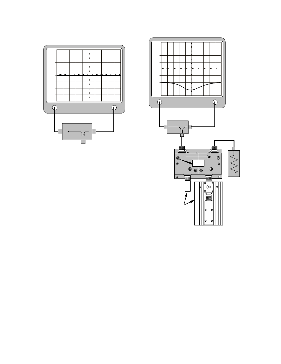
Bridge
Any good
quality
50 ohm
load
Dual
VHF
Isolator
Loads that will
be used during
actual operation
Analyzer
Input
Generate
Output
TUNE
+30
+20
+10
0
-10
-20
-30
1
5
3
4
6
2
Figure 4: Tuning for maximum return loss.
RLB - 150 Bridge
Analyzer
Input
Generate
Output
+30
+20
+10
0
-10
-20
-30
Reflected
Source
Load
To device to be tested.
This connector left open
for setting 0 dB reference.
Figure 3: Proper hookup of RLB-150 Bridge.