Power in/out, Insertion loss – Bird Technologies 81-37-25 Series User Manual
Page 12
TX RX Systems Inc. Manual 7-9095-3 01/17/06 Page 8
500
400
300
250
200
150
125
100
75
50
50
75
100
125
150
200
250
300
400
500
7.0
6.5
6.0
5.5
5.0
4.5
4.0
3.5
3.0
2.5
2.0
1.5
1.0
.50
.25
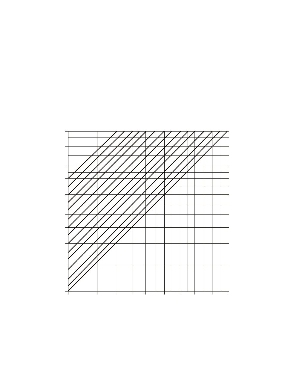
The graph below offers a convenient means of determining the insertion loss of filters, duplexers,
multicouplers and related products. The graph on the back page will allow you to quickly determine
VSWR. It should be remembered that the field accuracy of wattmeter readings is subject to
considerable variance due to RF connector VSWR and basic wattmeter accuracy, particularly at low
end scale readings. However, allowing for these variances, these graphs should prove to be a useful
reference.
POWER IN/OUT
VS
INSERTION LOSS
INSERTION LOSS (dB)
INPUT PO
WER (W
atts)
OUTPUT POWER (Watts)
FOR LOWER POWER LEVELS
DIVIDE BOTH SCALES
BY 10 (5 TO 50 WATTS)