Bird Technologies 81-37-25 Series User Manual
Page 8
TX RX Systems Inc. Manual 7-9095-3 01/17/06 Page 4
3) Switch to the Display Menu and select
“REF”. The trace should appear at the 0 dB
level.
SETTING 0 DB RETURN LOSS REFERENCE
Set the A-7550 (see Figure 3) for the desired fre-
quency and bandwidth. Connect the Return Loss
Bridge to the A-7550 but leave the LOAD por t
open. Repeat steps 1, 2, and 3 above.
4) Set the A-7550 for 10 dB per division and set a
zero dB return loss reference as outlined in
paragraph 2.
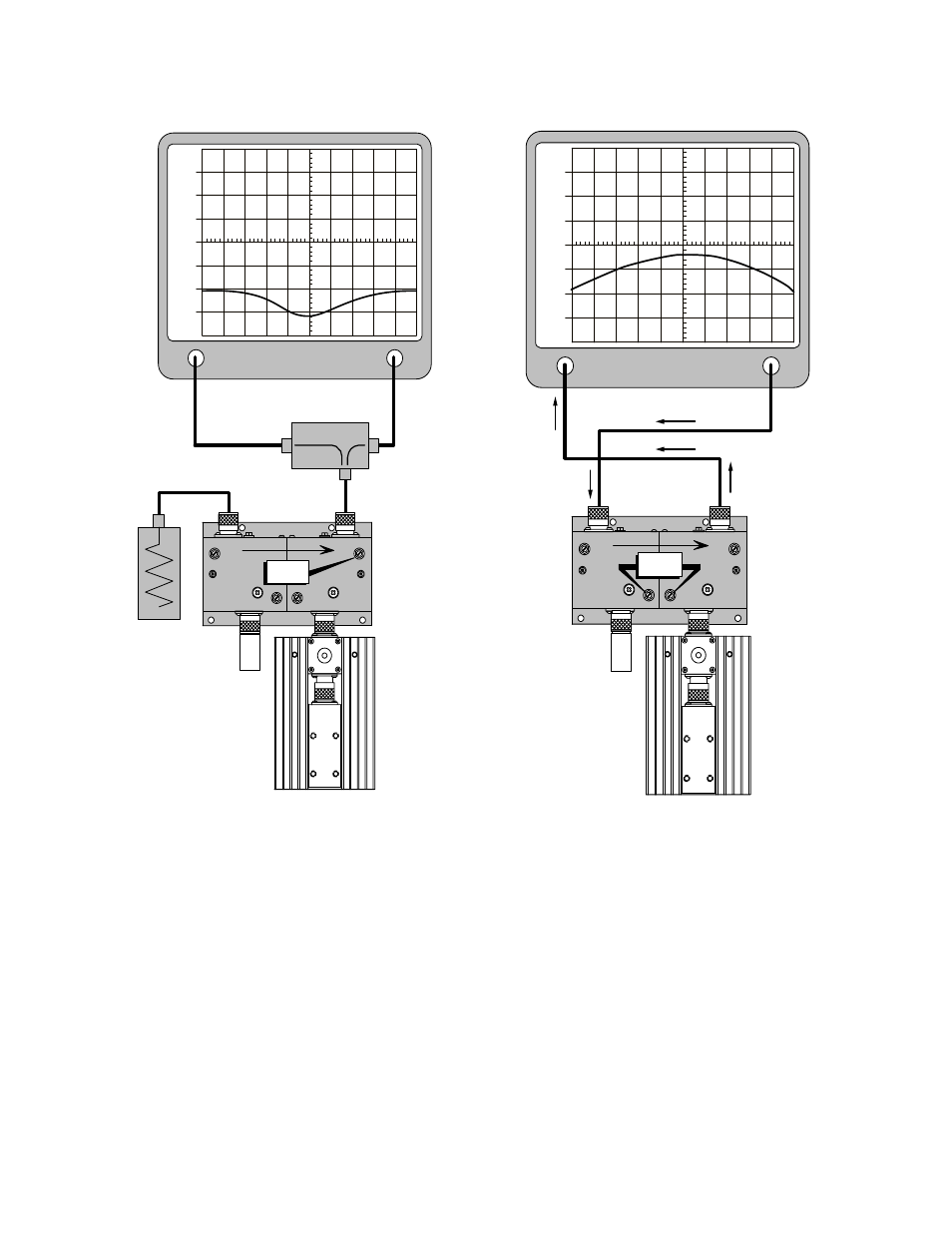
5) With the equipment connected as in Figure 4,
adjust tuning capacitor #1 for maximum return
loss at the desired center frequency.
6) Reversing the bridge and load connections as
shown on Figure 5, adjust capacitor 2 for maxi-
mum return loss at the desired center fre-
quency.
Analyzer
Input
Generate
Output
TUNE
+6
+4
+2
0
-2
-4
-6
1
5
3
4
6
2
RF
Figure 6: Tuning for passband symmetry.
Bridge
Analyzer
Input
Generate
Output
TUNE
+30
+20
+10
0
-10
-20
-30
1
5
3
4
6
2
Figure 5: Tuning for maximum return loss.