Rf power measurements, Figure 5 measurement direction – Bird Technologies 4412A User Manual
Page 18
8
RF Power Measurements
RF power measurements are made with plug-in elements inserted. Refer to
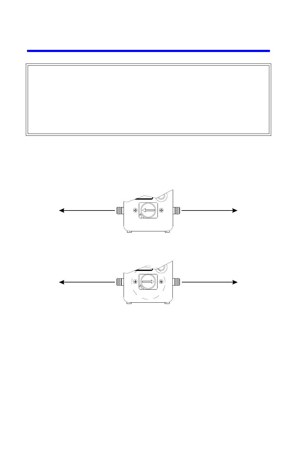
Figure 5 Measurement Direction
Forward power is indicated when the arrow on the element points in the direc-
tion of power flow; i.e., from transmitter to load.
Reflected power measurements are made with the element rotated 180° and
the arrow pointing toward the transmitter.
When the power measurements are being made, make sure the element is
rotated fully so that the element’s stop pin rests against the stop on the line sec-
tion, either in the forward or reflected position. Also be sure that the lock in the
lower left hand corner of the casting face presses on the shoulder of the plug-in
element to keep it in proper alignment and assure a good contact with the DC
connection and between the lower edge of the element and line section body.
WARNING
Exposure to RF power radiation and the possibility of RF shock or burns exist
under some operating conditions. Always turn off transmitter when
connecting or disconnecting wattmeter. Be sure transmission line is
terminated into a load or antenna. When a Plug-In Element is removed from
the RF line socket, the line section center conductor is exposed. Do not put
fingers or other objects into the plug-in element socket while RF power is
applied.
To Load
To Transmitter
To Load
To Transmitter
Forward Power Measurement
Reflected Power Measurement