Figure 10 replacing the instrumentation module, Replacing the quick-change connectors – Bird Technologies 4314C User Manual
Page 39
27
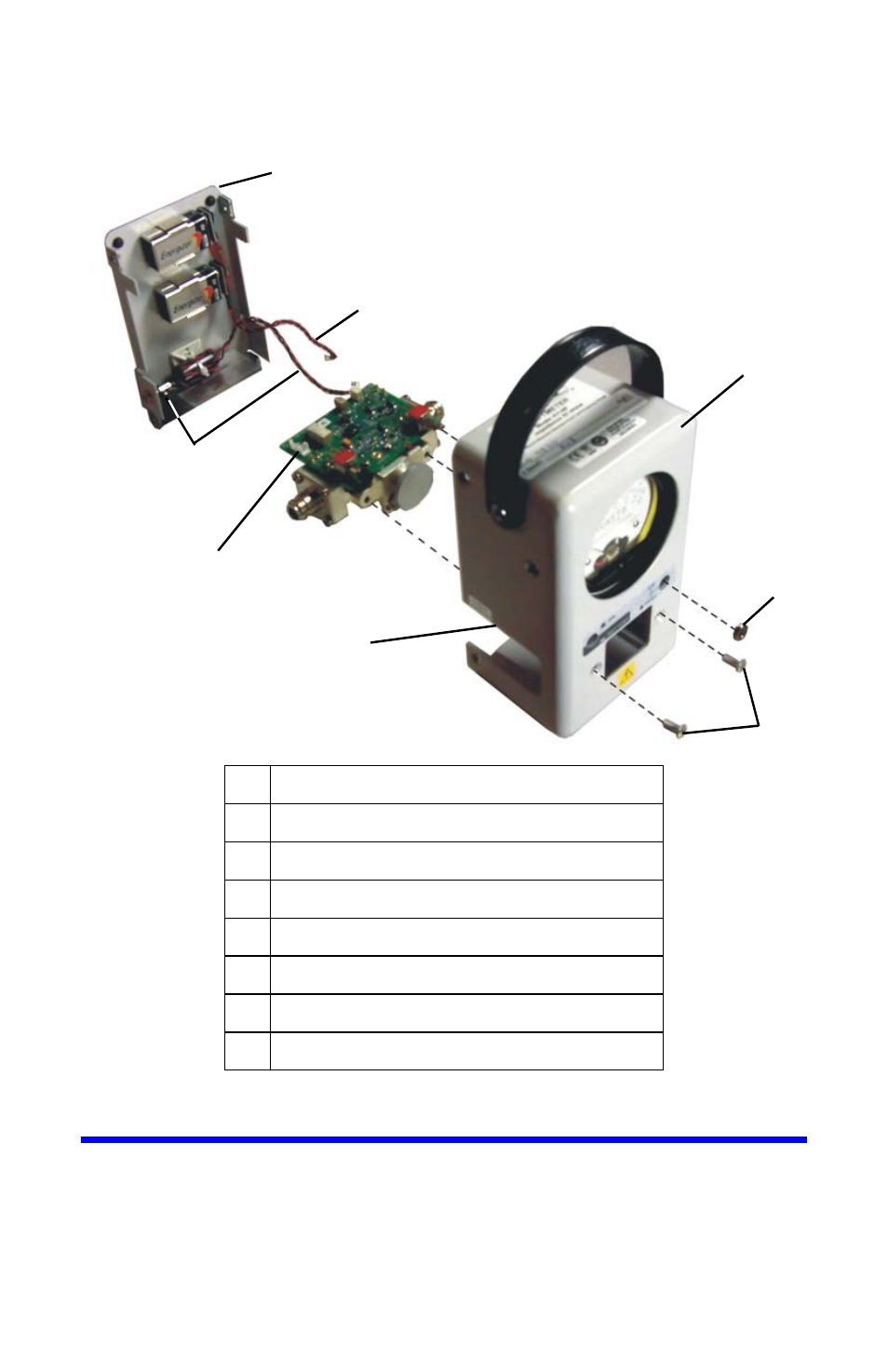
Figure 10 Replacing the Instrumentation Module
Replacing the Quick-Change Connectors
1.
Remove the four 8-32 screws from each corner of the square flange on the
connector.
2.
Pull the connector straight outward.
3.
Install the new connector by reversing this procedure.
1
Dressnut
2
Mounting Screws
3
Meter Wire Assembly (hidden from view)
4
Instrumenation Module
5
DC Jack Assembly
6
Housing Cover Assembly
7
Battery Cable Assembly
8
Housing Assembly
2
1
3
7
5
4
6
8
See also other documents in the category Bird Technologies Accessories communication:
- SK-4000-TC-Manual (56 pages)
- SK-4000-TC-Datasheet (2 pages)
- SH-36S-Manual (206 pages)
- SH-36S-Datasheet (4 pages)
- SH-36S-PC-Manual (130 pages)
- SH-36S-PC-Datasheet (2 pages)
- SH-36S-PC-Quick Start (2 pages)
- SH-36S-RM-Datasheet (2 pages)
- SA-3600XT-Manual (112 pages)
- SA-3600XT-Datasheet (2 pages)
- AT-500-Manual (73 pages)
- AT-500-Datasheet (2 pages)
- AT-800-Manual (74 pages)
- 89-83F-02-03-Manual (2 pages)
- 89-83F-02-03-Datasheet (1 page)
- 8251 Series-Datasheet (1 page)
- 8251 Series-Manual (30 pages)
- DA10 VHF Series-Datasheet (2 pages)
- DA10 VHF Series-Manual (47 pages)
- 8865SC13-Datasheet (2 pages)
- 8865SC13-Manual (28 pages)
- 8890-300SC13-Manual (28 pages)
- 8921SC13-Manual (28 pages)
- 8931-115SC13-Manual (34 pages)
- BDS-Datasheet (2 pages)
- BDS-Manual (98 pages)
- SCC7 Series-Datasheet (2 pages)
- SCC7 Series-Manual (45 pages)
- MSCC7 Series-Datasheet (2 pages)
- MSCC7 Series-Manual (35 pages)
- SCC8 Series-Datasheet (2 pages)
- SCC8 Series-Manual (47 pages)
- 4020 Series-Datasheet (1 page)
- 4020 Series-Manual (4 pages)
- 4027A Series-Datasheet (2 pages)
- 4027A Series-Manual (6 pages)
- 4027F Series-Datasheet (2 pages)
- 4027F Series-Manual (6 pages)
- 4028 Series-Datasheet (2 pages)
- 4028 Series-Manual (6 pages)
- 7022-Datasheet (4 pages)
- 7022-Manual (27 pages)
- ACM Series-Datasheet (2 pages)
- ACM Series-Manual (40 pages)
- BPME Series-Datasheet (4 pages)