Remote installation, Figure 7 panel cut for mounting rf body – Bird Technologies 4527 User Manual
Page 24
12
Remote Installation
Note: To replace the RF line section, reverse these steps.
1.
Unscrew the four 8-32 flat head screws securing the back cover.
2.
Grasp the back cover by the side tabs behind the line connectors and pull
straight back to remove it.
3.
Remove the two 10-32 oval screws on the front of the housing.
4.
Slide the line section out of the housing.
Note: Do not loosen the two oval screws on the sides of the housing
in line with the meter. These hold the shock ring in place.
5.
Replace the cable attaching the line section to the meter with one of suffi-
cient length to complete the remote installation.
In some systems it may be desirable to have two or more line sections perma-
nently installed. In this case, one set of elements and one meter can be used to
measure several separate RF transmission lines. Additional RF line sections are
available.
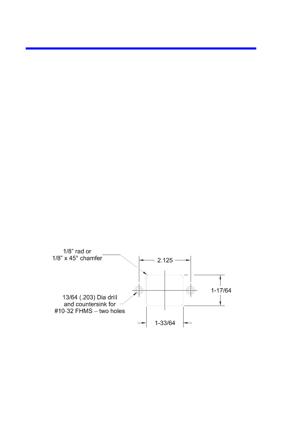
The RF line section of the Bird 43 lends itself very readily to panel mounting. A
layout for the panel cut is given in Figure 7. The thickness of the panel should be
about
1
⁄
4
inch. On thinner panels, build up the thickness with pads or washers to
achieve a flush-face mounting. Attach the line section so that the finger catch is
in the most accessible position.
Figure 7 Panel Cut for Mounting RF Body