Using a swivel flanged coupling, Figure 5 swivel flanged coupling, Using a unflanged coupling – Bird Technologies 8890-320 Series User Manual
Page 20: Figure 6 unflanged coupling, Using an ac power hookup
8
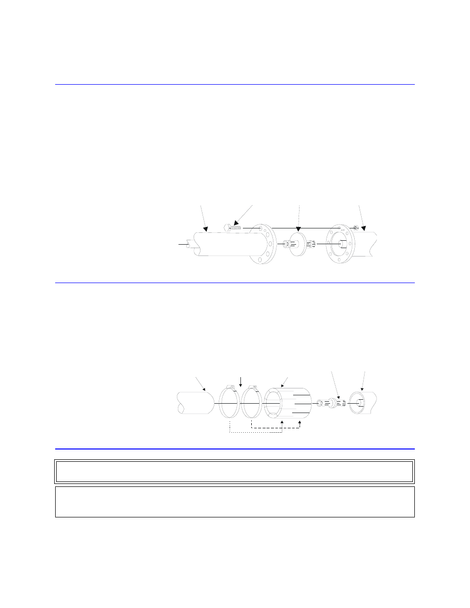
Using a Swivel Flanged Coupling
1.
Insert the center bullet.
2.
Push it in until it is fully seated.
3.
Connect the coaxial input in a straight line
4.
Push, carefully, on the center conductor to close.
Note: The swivel flange on the load makes connection independent of the
orientation of the fixed flange on the coaxial input outer conductor.
5.
Insert the bolt sets and tighten evenly all around to transmission line manufacturer’s
recommended torque.
Note: Use all of the bolts.
Figure 5 Swivel Flanged Coupling
Using a Unflanged Coupling
1.
Insert the center bullet
2.
Push until it sets the midpoint nibs.
3.
Position the outer sleeve, with clamping bands, over the input connector.
4.
Set the transmission line snugly against the coupling stops.
5.
Position the clamping bands evenly about 3/4” from the ends of the sleeve.
6.
Tighten the clamping bands.
Figure 6 Unflanged Coupling
Using an AC Power Hookup
AC power is only required if the blower assembly is installed. The AC power supply required is 115/230 V, depending
on the blower, @ 50/60 Hz, 1
φ. The blower is equipped with an IEC 320 “cold” (65 °C) AC inlet.
BOLT
BULLET
LOAD
RF COAXIAL LINE
RF COAXIAL
LINE
CLAMPING
BANDS
CONNECTOR
SLEEVE
BULLET
LOAD
WARNING
Turn off AC power and RF power when attaching the power cable.
CAUTION
Check the local electrical code for proper AC hookup prior to operation of the unit. Make sure the neutral or return
hookup is only used for that purpose.