Chapter 2 theory of operation, Load resistor, Coolant – Bird Technologies 8890-320 Series User Manual
Page 15: Thermal interlock, Blower assembly, Figure 3 blower plugs
3
Chapter 2
Theory of Operation
Load Resistor
Bird 8890 series loads consist of a thin-film-on-ceramic resistor immersed in a dielectric coolant. The resistor, individu-
ally selected for its accuracy, is enclosed in a special housing. When surrounded by the coolant, this produces a uni-
form, practically reflectionless line termination over the specified frequencies.
Coolant
The load is cooled by natural fluid and air convection currents. The coolant, chosen for its dielectric and thermal
characteristics, carries heat from the resistor to the walls of the cooling tank, where radiator fins surrounding the
tank transfer the heat to the air.
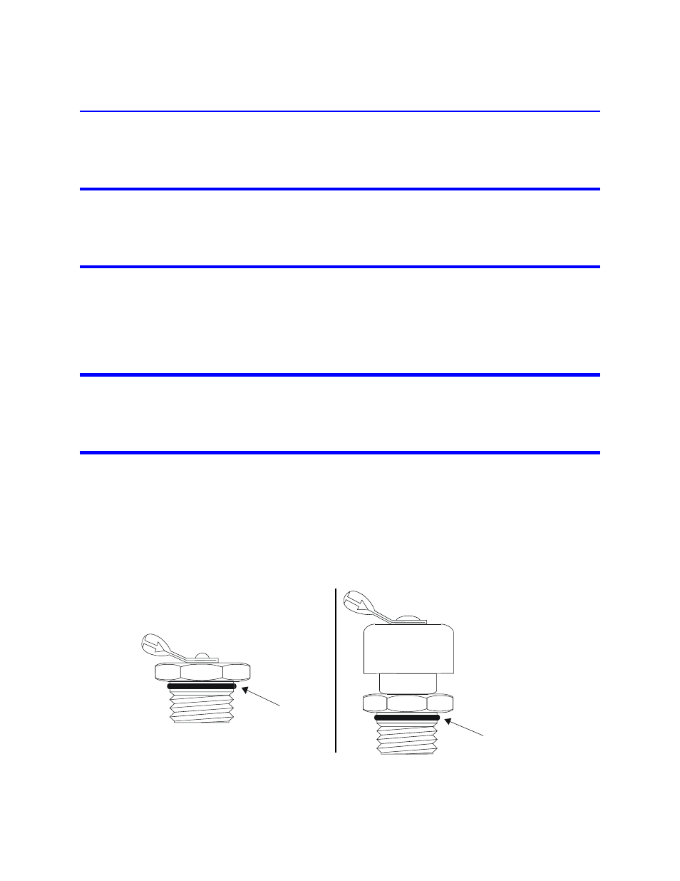
When the coolant is heated, thermal expansion causes an increase in the internal pressure. The vent plug (Figure 3,
Detail “B”) relieves this pressure while protecting the opening from dirt or other contaminants.
Thermal Interlock
When installed, a passive, normally closed over-temperature thermoswitch opens above the maximum safe load
temperature of 236 °C (457 °F), turning off transmitter power. The interlock will not permit use of the transmitter
until the load has reached a safe temperature.
Blower Assembly
When installed, the blower assembly provides forced airflow with two blowers. Baffles direct the airflow from the
blowers over the radiator fins, doubling the heat transfer efficiency.
Example - A 2.5 kW load will safely dissipate 5 kW. A passive,
normally open control thermoswitch closes when the coolant reaches 155 °C (311 °F), turn-
ing the fans on.
The baffles interfere with the free flow of normal air currents, causing a 50% reduction in heat transfer efficiency if
the forced airflow is stopped. Thus, a 2.5 kW load will have its maximum power dissipation reduced to 1.25 kW.
Figure 3 Blower Plugs
O-ring seal
O-ring seal
DETAIL “A” -
Shipping Plug
DETAIL “B” -
Vent Plug