Interlock connection, Figure 4 thermoswitch assembly – Bird Technologies 8921SC13-Manual User Manual
Page 17
Installation
7
Interlock
Connection
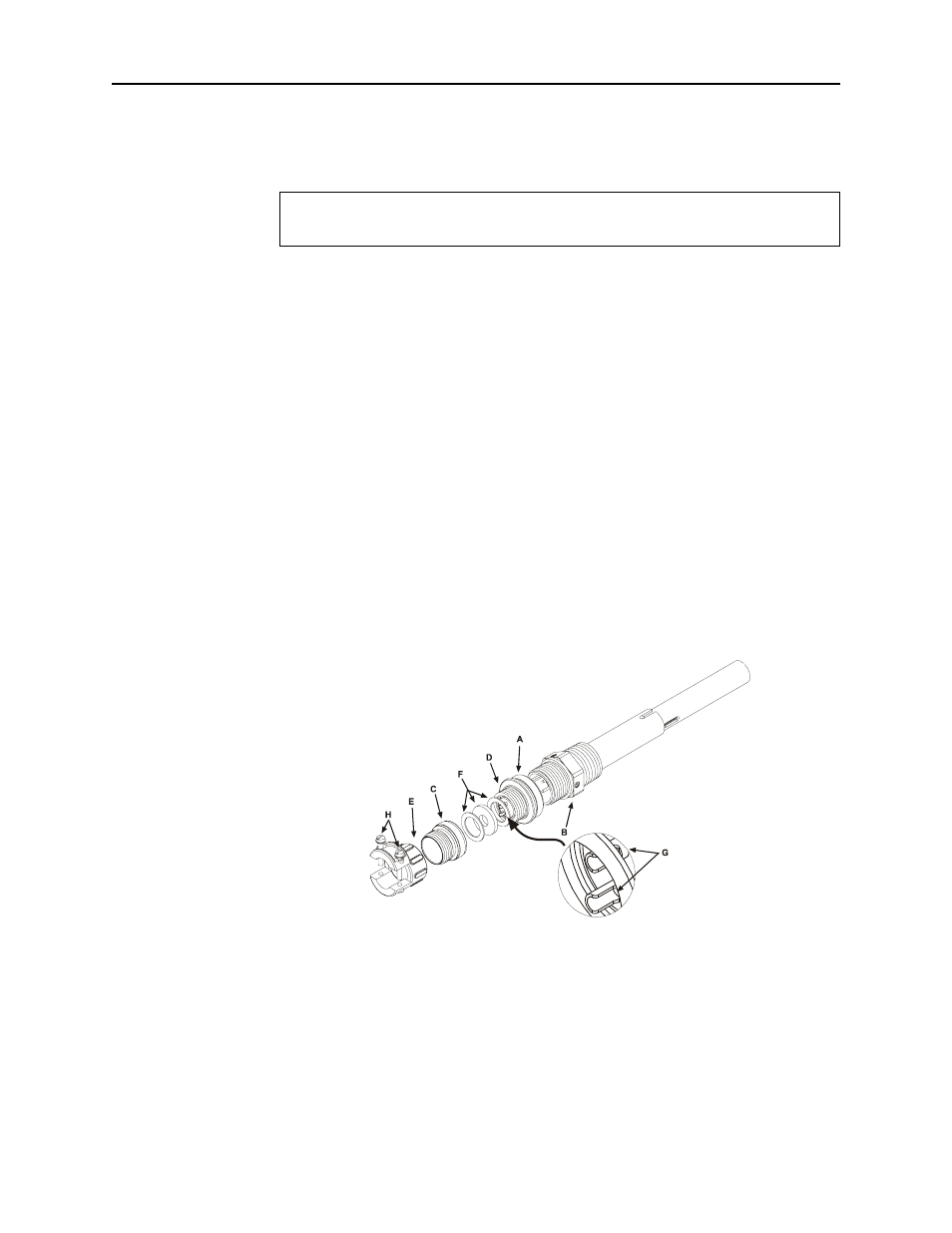
Connect the thermoswitch to the interlock as follows (see Figure 4):
1. Unscrew the large knurled ring-nut (A) at the lower end of the
coupling jack assembly. Pull it off the thermoswitch jack (B).
Unscrew the small knurled cover fitting from the base plug (D) of
the connector to release the base.
2. Thread the control switch wires through the clamp (E) with the
washers (F) inside and with its threaded fitting in place. Service
the control switch wire with short tips and put spaghetti sleeves
over the wire ends if necessary.
3. Securely solder the control switch leads to the lugs (G) of the
connector base.
NOTE: The ring-nut (A) must be in place over the base plug (D)
with the knurled end facing out.
4. Screw on the cover ring, then fasten the cable clamp (E) in place
and tighten both yoke screws (H).
5. Put the plug back on the thermoswitch and tighten the nut (A).
CAUTION
If installed, connect optional interlock before applying RF power.
Figure 4
Thermoswitch
Assembly