Using a “qc” connector coupling, Using a 13-30 coupling, Using a swivel flanged coupling – Bird Technologies 8251 Series-Manual User Manual
Page 17: Figure 5 swivel flanged coupling, Using a unflanged coupling, Figure 6 unflanged coupling
7
Using a “QC” Connector Coupling
Use a 50 ohm coaxial cable such as RG-218/U or -220/U (-17A or -19A), appropriate for the frequency and power
level of operation.
Note: Use a cable connector which will mate with the one on the load.
Using a 13-30 Coupling
Use 50 ohm coaxial cable such as RG-8A/U, RG-9U, RG-213/U, or equivalent with a male 13-30 plug.
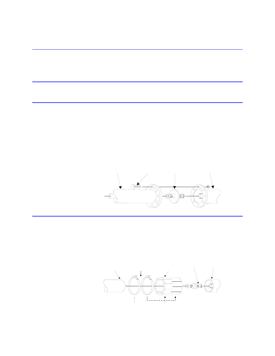
Using a Swivel Flanged Coupling
1.
Insert the center bullet.
2.
Push it in until it is fully seated.
3.
Connect the coaxial input in a straight line
4.
Push, carefully, on the center conductor to close.
Note: The swivel flange on the load makes connection independent of the
orientation of the fixed flange on the coaxial input outer conductor.
5.
Insert the bolt sets and tighten evenly all around to transmission line manufacturer’s
recommended torque.
Note: Use all of the bolts.
Figure 5 Swivel Flanged Coupling
Using a Unflanged Coupling
1.
Insert the center bullet
2.
Push until it sets the midpoint nibs.
3.
Position the outer sleeve, with clamping bands, over the input connector.
4.
Set the transmission line snugly against the coupling stops.
5.
Position the clamping bands evenly about 3/4” from the ends of the sleeve.
6.
Tighten the clamping bands.
Figure 6 Unflanged Coupling
After the transmitter has been connected to the load, proceed according to the transmitter manufacturer’s instruc-
tions. When reconnecting the antenna, it may be necessary to slightly readjust the transmitter due to differences in
VSWR between the load and the antenna system.
BOLT
BULLET
LOAD
RF COAXIAL LINE
RF COAXIAL
LINE
CLAMPING
BANDS
CONNECTOR
SLEEVE
BULLET
LOAD